Transcription of III. Three-Phase Circuits
1 III. Three-Phase CircuitsAlmost all electric power generation and most of the power transmission in the world is in the form of Three-Phase AC Circuits . A Three-Phase AC system consists of Three-Phase generators, transmission lines, and are two major advantages of Three-Phase systems over a single-phase system:a) More power per kilogram of metal form a Three-Phase machine;b) Power delivered to a Three-Phase load is constant at all time, instead of pulsing as it does in a single-phase first Three-Phase electrical system was patented in 1882 by John Hopkinson - British physicist, electrical engineer, Fellow of the Royal Systems1. Generation of Three-Phase voltages and currentsA Three-Phase generator consists of three single-phase generators with voltages of equal amplitudes and phase differences of 120.
2 Each of Three-Phase generators can be connected to one of three identical way the system would consist of three single-phase Circuits differing in phase angle by 120 .The current flowing to each load can be found as ZVI 0000120120240240 ABAVIIZVIIZVIIZ Therefore, the currents flowing in each phase areWe can connect the negative (ground) ends of the three single-phase generators and loads together, so they share the common return line (neutral).The current flowing through a neutral can be found as00000 00000120240cos()sin()cos(120 )sin(120 )cos(240 )sin(240 )cos() cos(120 ) cos(240 )sin() sin(120 ) sin(240 )cos(NABCI III IIIIjIIjIIjIIjII 00 0 000 0 0) cos() cos(120 ) sin() sin(120 ) cos() cos(240 ) sin() sin(240 )sin() sin() cos(120 ) cos() sin(120 ) sin() cos(240 ) cos() sin(240 )jI 1313cos()cos()sin()cos()sin()22221313sin ()sin()cos()sin()cos()22 220 NIIjI which is simplified to beSo, as long as the three loads are equal, the return currentin the neutralis zero!
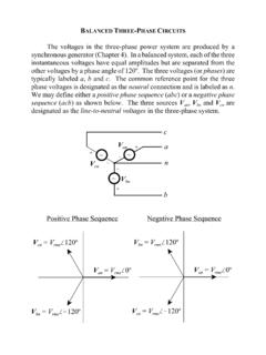
3 Such Three-Phase power systems (equal magnitude, phase differences of 120 , identical loads) are called a balanced system, the neutral is unnecessary!Phase Sequenceis the order in which the voltages in the individual phases Connection TypesThere are two types of connections in Three-Phase Circuits : Y(Wye) and (Delta)Each generator and each load can be either Y-or -connected. Any number of Y- and -connected elements may be mixed in a power quantities voltages and currents in a given quantities voltages between the lines and currents in the lines connected to the ) Y-connectionAssuming a resistive current in any line is the same as the current in the corresponding are:00013330120222231322303aabbVV VVVV jVVjVjVVV 30 3 VVab 90 3 VVbc 210 3 VVca IIL Magnitudes of the line-to-line voltages and the line-to-neutral voltages are related as.
4 VVLL3 In addition, the line-to-line voltages are shifted by 30 with respect to the phase a connection with abcsequence, the voltage of a line leadsthe phase voltage by 30 as shown in the ) -connectionAssuming a resistive 0000120240abbccaIIIIII Line-to-line voltage magnitudes are the same as the phase are: 30 3 IIa 150 3 IIb 270 3 IIc VVLL 00013024022333132222330abcaaII IIIIIIjIIj I Ij Magnitudes of the line and phase currents are related as: IIL3 For the connections with the abcphase sequences, the current of a line lagsthe corresponding phase current by 30 as shwon in the addition, the line currents are shifted by 30 with respect to the phase (Y) Connected LoadDelta ( ) Connected Load -connected loads are most common to allow easy addition and removal of loads in each phase Y-connected sources are most common to avoid circulating currents when there is a small UseWhat do you want to use in practice?
5 [Most common usage]For a balanced Y-connected load with the impedance Z = Z and phase voltages as:c) Power relationship00()2 sin()2 sin(120 )( )2 sin(240 )anbncnvtVtvtVtvtVt The currents can be found as:00()2 sin()()2 sin(120)( )2 sin(240)abcitItitItitIt Simplify the above equations using ()()()pt vtit Therefore, the instantaneous power supplied to each phase is:0000()() () 2 sin( )sin()()() () 2 sin(120 )sin(120)( )( ) ( )2sin(240 ) sin(240)aanabbnbccncpt v tit VIttpt v titVIttpt v titVItt 1sin sincos() cos()2 00( )coscos(2)( )coscos(2240)( )coscos(2480)abcpt VItpt VItpt VIt The instantaneous power is:The total power on the load is given by()()()3 cos()totabcpt ptptVptI The pulsing components cancel each other because of 120 phase shifts, so the total poweron the load is figure shows:a) The instantaneous power in each ) The total power supplied to the load (which is constant)Phase quantities in each phase of a Y-or Real Power:Reactive Power.
6 23sin3sinQVIIZ Apparent Power:233 SVI IZ NOTE: These equations are valid for balanced line quantities of a consumed by a load:since for this loadthereforeNOTE: These equations are valid for balanced 3 LLLIIandVV 3cos3 LLLVPI Finally3cosLL LPVI Deriving line quantities of a consumed by a load:since for this loadthereforeNOTE: These equations are valid for balanced 3cos3 LLLVPI Finally3cosLL LPVI 3 LLLIIandV V Same as for a Y-connected load!Line quantities for a Y-or Power:Reactive Power:Apparent Power:NOTE: These equations are valid for balanced LPVI 3sinLL LQVI 3 LLLSVI Reminder: is the load (or impedance) angle, the angle between the phase voltage and the phase ) Analysis of balanced systemsA -connected circuit can be analyzed via the transform of impedances by the Y- transform.
7 For a balanced load, it states that a -connected load consisting of three equal impedances Zis equivalent to a Y-connected load with the impedances Z/3. This equivalence implies that the voltages, currents, and powers supplied to both loads would be the a 208-V Three-Phase ideally balanced system shown below, Find:a) The magnitude of the line current ILb) The magnitude of the load s line and phase voltages VLLand V L;c) The real, reactive, and the apparent powers consumed by the load;d) The power factor of the , the generator and the load are Y-connected, therefore, it s easy to construct a per-phase equivalent ) Phase current:00000120 0120 0120 ( ) (129) b) Phase voltage over the load:0000( )(129) ( )(15 ) and the maignitude of the line voltage on the c) The real power consumed by the load:03cos3 cos The reactive power consumed by the load:03sin3 sin varloadQVI The apparent power consumed by the load:33 2839loadSVIVA d) The load power factor.
8 0coscos e) One-line diagramsSince, in a balanced system, three phases are similar except of the 120 phase shift, power systems are frequently represented by a single line showing all three phases of the real is a one-line diagrams usually include all the major components of a power system: generators, transformers, transmission lines, we can neglect the impedance of the transmission line, an important simplification in the power calculation is the generator voltage in the system is known, then we can find the current and power factor at any point in the system as line voltages at the generator and the loads will be identical since the line is and reactive powers on each total real and reactive powers supplied to all loads from the point system power factor at that point using the power triangle and phase currents at that can treat the line voltage as constant and use the power triangle method to quickly calculate the effect of adding a load on the overall system and power factor.