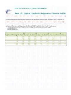
Transcription of IV. Three-Phase Transfomers - Hacettepe
1 1IV. Three-Phase TransfomersThe majority of the power generation/distribution systems in the world are 3-phase systems. The transformers for such circuits can be constructed either as a 3-phase bank of independent identical transformers (can be replaced independently) or as a single transformer wound on a single 3-legged core(lighter, smaller, cheaper and slightly more efficient). Three-Phase Transfomers2We assume that any single transformer in a 3-phase transformer (bank) behaves exactly as a single-phase transformer. The impedance, voltage regulation, efficiency, and other calculations for 3-phase transformers are done on a per-phase basis, using the techniques studied previously for single-phase possible connections for a 3-phase transformer bank are:1) Y-Y2) Y- 3) - 4) -YCommon Three-Phase transformer connections.
2 The transformer windings are indicated by the heavy ) Y-Y connectionThe primary voltage on each phase of the transformer is:3 LPPVV The secondary phase voltage is:3 LSSVV The overall voltage ratio is:33 PLPLSSVVaVV The Y-Y connection is seldom used as it has two very serious problems:a) If loads on one of the transformer circuits are unbalanced, the voltages on the phases of the transformer canbecome severely ) The third harmonicissue. The voltages in any phase of an Y-Y transformer are 120 apart from the voltages in any other phase. However, the third-harmonic components of each phase will be in phase with each other. Nonlinearities in the transformer core always lead to generation of third harmonic!These components will add up resulting in large (can be even larger than the fundamental component) third harmonic problems can be solved by one of two techniques:i) Solidly ground the neutralof the transformers (especially, the primaryside).
3 The third harmonic will flow in the neutral and a return path will be established for the unbalanced ) Add a third -connected winding. A circulating current at the third harmonic will flow through it suppressing the third harmonic in other ) Y- connectionThe primary voltage on each phase of the transformer is:3 LPPVV The secondary phase voltage is:The overall voltage ratio is:LSSVV 33 PLPLSSVVaVV The Y- connection has no problem with third harmonic components, sincethey are consumed in a circulating current on the side. It is also more stable to unbalanced loads since the partially redistributes any imbalance that problem associated with this connection is that the secondary voltage is shifted by 30 with respect to the primary voltage. This can cause problems when paralleling 3-phase transformers since transformers secondary voltages must be in-phase to be paralleled.
4 Therefore, we must pay attention to these the , it is common (actually it is a standard now) to make the secondary voltage to lag the primary voltage. The connection shown in the previous slide will do Y- connection is generally used in stepping downfrom a high voltage to a medium or low voltage. One reason is that a neutral is thereby provided for grounding on the high-voltage side, a procedure which can be shown to be desirable in many ) -Y connectionThe primary voltage on each phase of the transformer is:The secondary phase voltage is:The overall voltage ratio is:PLPVV 3 LSSVV 33 PLPLSSVVaVV The -Yconnection has the same advantages and the same phase shift as the Y- -Yconnection is commonly used for stepping upto a high ) - connectionThe primary voltage on each phase of the transformer is:The secondary phase voltage is:The overall voltage ratio is.
5 PLPVV LSSVV PLPLSSVVaVV The - connection has no phase shift and no problems with unbalanced loads or - connection has the advantage that one transformer can be removed for repair or maintenance while the remaining tow continue to function as a Three-Phase bank with the rating reduced to 58% of that of the original bank; this is known as the open-delta, or V, Three-Phase Transformer fixed line-to-line voltages and total fixed kVA rating of the 3-phase transformer, the kVA rating of each transformer is 1/3rdof total kVA rating of bank regardless of the connection and current values of individual transformers depend on connection type (Yor ) computations involving 3-phase transformer banks can be made by dealing with only one phase and recognizing that condition are same for other 3 phases except a 120 phase are carried out on a per-phase Yline-to-neutral basis, since the transformer impedances in a Y-connected can be added directly in series with transmission line impedances of transmission lines can be referred from one side to other by the use of square of ideal line-to-line voltage ratio of the dealing with Y- or -Ybanks, all quantities should be referred to Y-connected side for dealing with - banks in series with transmission lines, it is convenient to replace -connected transformer impedance into Y-connected per-unit system applies to the 3-phase transformers as well as to single-phase transformers .
6 Per-Unit System for Three-Phase TransfomersTherefore, the base phase current and impedance of the transformer are1,3basebaseSS 1,,,,3basebbasebaassbaeeseSVSIV 2,1,,23basebasbasebasebaseeVZSVS If the total base VA value of the transformer bank is Sbase, the base VA value of one of the transformers will be8 The line quantities on 3-phase transformer banks can also be represented in per-unit system. ,,LbasebaseVV If the windings are in Y:,,3 LbasebaseVV And the base line current in a 3-phase transformer bank is:,,3baseLbaseLbaseSIV The application of the per-unit system to 3-phase transformer problems is similar to its application in single-phase situations. The voltage regulation of the transformer bank is the the windings are in :Ex 50 kVA, 13800/208V -Ytransformer has a resistance of 1% and a reactance of 7% per ) What is the transformer s phase impedance referred to the high voltage side?
7 B) What is the transformer s voltage regulation at full load and pf lagging, using the calculated high-side impedance?c) What is the transformer s voltage regulation under the same conditions, using the per-unit system?a) The high-voltage side of the transformer has the base voltage 13 800 V and a base apparent power of 50 kVA. Since the primary side is -connected, its phase voltage and the line voltage are the same. The base impedance is: 22,33 13 80011 42650 000basebasebaseVZS 9 The per-unit impedance of the transformer is:Therefore, the high-side impedance in ohms is:b) The voltage regulation of a 3-phase transformer equals to a voltage regulation of a single transformer:, puZjpu , 11 426 114800eqeq pu baseZZZjj 100%PSSVaVVRaV The rated phase current on the primary side can be found as.
8 50 13 800 SIAV The rated phase voltage on the secondary of the transformer isWhen referred to the primary (high-voltage) side, this voltage becomesAssuming that the transformer secondary winding is working at the rated voltage and current, the resulting primary phase voltage isThe voltage regulation, therefore, is2081203 SVV '13800 SSVaVV 1113 800 0 cos ( )800 cos ( )14 14 506 14 506 13 800100%100% 800 PSSVaVVRaV 10c) In the per-unit system, the output voltage is 1 0 , and the current is 1 cos-1( ). Therefore, the input voltage isThus, the voltage regulation in per-unit system will be111 1 cos ( ) 1 cos ( ) The voltage regulation in per-unit system is the same as computed in 2400:240V single-phase transformers connected in - and supplied with power through a 3-phase feeder ( cable) connected at high-voltage side whose reactance is /phase.
9 The equivalent reactance of each transformer referred to high-voltage side is /phase. Other circuit resistances are negligible. At its sending end ( primary-side), the feeder is connected to the secondary terminals of a Y- connected 3-phase transformer whose rating is 500kVA 24000:2400V. The equivalent reactance of sending end transformer is /phase referred to 2400V side. The voltage applied to primary of the sending end transformer is 24kV. A 3-phase short-circuit occurs at 240V terminals of the receiving end transformer ( load side). Compute the steady-state short-circuit current in the feeder wires, primary of receiving end and actual value of the short circuit current.