Transcription of IOL : POWER CALCULATION & SELECTION
1 21 Chapter - 3 IOL : POWER CALCULATION & SELECTIONP recise IOL POWER CALCULATION is essential for optimal benefits of implantsurgery. Prior to1975, IOL POWER was calculated on the basis of clinical history, refractive error prior to development of cataract. This led to errors inover 50% of cases. However, a number of formulae are now available to accuratelycalculate the IOL POWER required in a patient. All these formulae are based on anaccurate measurement of the corneal POWER and the axial IN USEThe original formulae were developed prior to 1980. They include thetheoretical formulae and regression formulae.
2 The commonly used formulae are theregression formulae, of which the most popular one is the SRK formula described bySanders D, Retzlaff J. and Kraff M. The formula is based on the following equation:P=A BL-CKwhere P is the implant POWER for emmetropia, L the axial length in millimeters, and Kthe average keratometric reading in diopters. A, Band C are constants. The value ofB is and that of C is P = A - 2. 5L - constant A varies with the implant design and the manufacturer. Be sureof the constant value of the IOL you are using while making the calculations. TheSRK formula has been found to be reasonably accurate for eyes with axial lengthsbetween 22mm and These eyes constitute approximately 75% of cases,while 14% of cases have axial lengths greater than mm, and 10% have axiallengths less than 22mm.
3 The modified formulae were developed to correct for errorsin these formulae occurring in long and short is for such 'too long' and 'too short' eyeballs that SRK II formula wasintroduced. The SRK II formula is a modification of the original SRK formula with theaddition of a correction factor that increases the lens POWER in short eyes anddecreases it in long suggested method of modification of SRK to SRK II is shown below:L (mm)Add to 'A' constantLess than + - + - + 1 Greater than formulae for emmetropia:These formulae are more complex than the original and the modifiedformulae.
4 The most striking difference is the manner in which the estimated anteriorchamber depth (ACD) value is calculated. The ACD value is a constant value in theoriginal formulae. It varies with the axial length in the modified formulae (decreasesin the shorter eye and increases in the longer eye). In the modern formulae, ACDvalue varies not only with axial length, but also with corneal curvature (being morewith steeper cornea and deep AC and vice versa). The commonly used modernformulae are the Holladay formula, the SRK-T formula and the Hoffer-Q keratometry is the most commonly used method to measure cornealcurvature.
5 It is fast, easy and is very accurate in most cases. Keratometry should bedone before axial length measurement, and for both eyes. Remember to calibratethe eyepiece for your refraction before recording measurements. The procedure ofkeratometry using the common Bausch and Lomb keratometer is given here. Thepatient is seated behind the keratometer, with the chin well positioned in the chin restand the head resting on the head band. The keratometer is directed towards the eyeto be examined and the other eye is occluded. The keratometer is focused on thecentral portion of the cornea using the focusing knobs.
6 The instrument is now rotatedto align the (-) signs in the same vertical meridian and the (+) signs in the samehorizontal meridian. This will determine the axis of the pre-existing astigmatism. Theleft drum is rotated to superimpose the (+) signs and the horizontal measurement isread out. The right drum is now rotated to superimpose the (-) signs and the verticalmeasurement reading is recorded. The Javal-Shi tz keratometer utilizes two mires toachieve the end point. IOL POWER CALCULATION formulae use the average corneal23power, K = average of the horizontal and the vertical readings.
7 It is important toremember that the keratometer has to be calibrated every 6 is advisable to repeat measurement if the keratometry (K) in either eye is less than 40 D or greater than 47 in K between the two eyes is greater than 1 cylinder does not correlate well with the refractive certain situations, like irregular corneal contour or previous refractive surgery, orwhen the surgeon wants to better evaluate the astigmatism, corneal topography maybe LENGTH MEASUREMENTSThe measurement of the axial length is best done with A-scan ultrasonography. Itcan be performed by an immersion technique or a contact technique.
8 The machineshould have a screen showing the spikes for ensuring correct measurement. Alwaystake measurement for both the contact technique, a drop of local anesthetic is instilled into each patient is examined in the seated position. The probe is positioned in front of theeye and the patient is asked to fixate on the red light in the probe. The probe is thenbrought forward to gently touch the cornea. Particular attention and care must betaken to ensure that the probe is not indenting the cornea. The probe is movedslightly up and down or to the side to optimize the echospikes displayed on themachine.
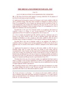
9 Either the operator or the machine selects the optimum pattern and thereading is immersion technique isperformed with the patient in thesupine position. Topical anesthetic isinstilled and a proper scleral shell ischosen. The 20 mm shell fits mosteyes. The flared edges of the scleralshell are placed between the lids andGood A-scan. Echos from left to right : cornea,anterior lens capsule, posterior lens capsule,retina,sclera,orbital fat24the cup is filled with fluid, preferably gonioscopic solution. The ultrasound probe isimmersed in the solution but kept 5-10 mm away from the cornea.
10 The patient isasked to look with the fellow eye at a fixation point on the ceiling. The probe is thengently moved till it is aligned with the optical axis of the eye and the a-scanechogram on the panel is adequate. The reading is then contact technique usually yields shorter measurement than theimmersion technique for various reasons. Most modern biometers calculate the axiallength based on separate sound velocities for different eye components (cornea,anterior chamber, lens, vitreous cavity).It is recommended that measurements be repeated if the axial length is less than mm or more than between the two eyes is more than length value seems wrong when compared with measurements should be repeated if following exist:a.