Transcription of Ion Implantation Technology for Image Sensors
1 Ion Implantation Technology for Image Sensors Nobukazu Teranishi1, 2, Genshu Fuse3, and Michiro Sugitani3 1: Laboratory of Advanced Science and Technology for Industry, University of Hyogo 1- 1-2 Koto, Kamigori, Ako-gun, Hyogo 678-1205 Japan 2: Research Institute of Electronics, Shizuoka University 3- 5-1 Johoku, Hamamatsu, 432-8011 Japan 3: Sumitomo Heavy Industries Ion Technology Co., Ltd. (SMIT) 1501 Imazaike, Saijo, Ehime 799-1362 Japan Abstract Ion Implantation Technology is reviewed mainly from a viewpoint of Image Sensors , which play a significant role for Implantation Technology development.
2 Image Sensors are so sensitive to metal contamination that it can detect even one metal per pixel. To reduce the metal contamination, the plasma shower using RF (radio frequency) plasma generation is a representative example. The electrostatic angular energy filter after the mass analyzing magnet is a highly effective method to get rid of contamination caused by the charge exchange process. The protection layer on the silicon is needed to protect the silicon wafer against the physisorbed metals. The thickness of protection layer should be determined by considering the knock-on depth.
3 In addition, the wafers should be cleaned up just after ion implantations and before thermal treatments. The damage by ion Implantation also causes blemishes. It becomes larger in the following conditions if the other conditions are the same; a. higher energy, b. larger dose, c. smaller beam size (higher beam current density), d. longer ion beam irradiation time, e. larger ion mass. To reduce channeling, the most effective method is to choose proper tilt and twist angles. The screen oxide method is not effective because it needs a thick oxide layer. Although the pre-amorphization method is good for channeling suppression, re-crystallization quality is not yet sufficient at present.
4 The zero-degree tilt Implantation has large variation because the channeling is sensitive to even small angle variation. For P+ pinning layer formation, the low-energy B+ Implantation method might have less metal contamination and damage, compared with the BF2+ method. Keywords: Image sensor , ion Implantation , metal contamination, damage, channeling 1. Introduction Solid-state Image sensor technologies have been advanced drastically these 4 decades, and they brought fruitful success in the market. The sales amount on Image Sensors achieved billion pieces in 2014 mainly because of the exponential growth of mobile phone market.
5 Image sensor applications are spreading anywhere besides the mobile phones. During the Image sensor evolution, various device technologies and process technologies have been developed. Among them, ion Implantation Technology is one of the most important process technologies for Image Sensors . From the opposite viewpoint, Image Sensors are a very important application for ion Implantation Technology development; Firstly, many ion Implantation steps are applied to fabricate specific structures, such as PPD (pinned photodiode) [1-3], special isolation structure [4], and to tune transistors at pixels [5].
6 Secondly, to obtain deep PD (photodiode), high energy implantations with a precise angle control are required, together with high aspect ratio resist patterns. In addition, a precise impurity profile formation is required to achieve a good signal electron transfer in PPD pixel. Thirdly, Image Sensors are very sensitive to metal contamination and crystal defects, which generate white defects (blemishes), because they have so low noise. In this paper, ion Implantation Technology is reviewed mainly from a viewpoint of Image Sensors . First, basics of ion Implantation Technology are explained in Section 2.
7 Then, metal contamination, damage and channeling, which are important topics for Image Sensors are discussed in Sections 3, 4 and 5, respectively. In Section 6, the P+ pinning layer formation methods are compared. 2. Basics of ion Implantation Technology Historically speaking, an ion Implantation process patent was submitted by W. Shockley in 1949 [6], who is the one of the inventors of transistors. It was applied to mass-production line in early 1970 s. Therefore, it can be said that it is rather a new process Technology . At first, ion implantations were used for threshold voltage control for MOS transistors.
8 Since then, they have been adapted for various purposes; a. Threshold voltage control. b. High density doping, such as source-drain formation. c. SIMOX (Separation by Implantation of Oxygen) [7]. Silicon dioxide layer is formed by oxygen Implantation to obtain SOI (silicon on insulator) wafer. d. Delamination [8]. High dose hydrogen Implantation forms a delamination layer, and thin silicon layer is split at temperature above 500 C. This phenomenon is applied to produce SOI wafers by wafer bonding method. e. Proximity gettering [9]. Oxygen or carbon is implanted to form gettering sites nearby the front active layer.
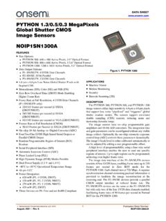
9 The reproducible gettering site formation is realized by the preciseness of ion Implantation , and the proximity gettering is powerful because the gettering sites are nearby the front side active area. f. Dangling bond termination [10]. Fig. 1. The rotating disk and wafer holders in the batch type ion implanters (courtesy to SMIT). Fluorine is implanted to terminate dangling bonds. Then, interface state GR (generation recombination) centers are reduced and leakage current is decreased. g. Amorphous formation [11]. High dose Implantation forms an amorphous layer. It decreases the channeling effect, which will be explained later.
10 It also helps re-crystallization and electrical activation during the annealing process after ion Implantation . h. Co- Implantation [12]. The impurity diffusion is suppressed if dopant atoms are implanted together with carbon, nitrogen or fluorine atoms. Focused ion beam (FIB), secondary ion mass spectroscopy (SIMS) also belongs to a category of the ion beam Technology . Ion Implantation has following important features; 1) The doping amount is precise enough over 5 decades. 2) The doping area is selected by using photo-resist patterns. 3) The doping profile or depth is controlled by the ion energy.


![[Product Information] Ver.1.0 IMX335LLN](/cache/preview/7/9/d/b/7/a/0/7/thumb-79db7a079fd0ce105d1ae95e9e1ae36e.jpg)