Transcription of IP Joystick Controller
1 Ver. 8/19 Page1 PTZO ptics IP Joystick Controller Third Generation IP Joystick Controller Installation & Operation Manual Please visit for the most up to date version of this manual Ver. 8/19 Page2 Table of Contents . Precautions Safety Page 3 Page 3 What s in the Page 3 Physical Descriptions Top View of Page 4 Back View of Page 5 Hardware Setup Page 5 Page 5 Quick Start Basic Operation Initial setup for Joystick Controller on a Page 6 Adjusting the default Page 6 Assigning a static IP to the Joystick Page 7 Using the Joystick Adding Page 8 Removing Page 9 Using Web Page 9 Switching between Page 10 Controlling Page 11 Setting and Calling Page 12 Web Interface Logging Page 12 Page 13 Page 14 Page 15 Factory Page 16 Page 16 Page 17 Page 18 Ver.
2 8/19 Page3 Precautions . Safety Tips . Please read this manual carefully before using the Joystick Controller . Avoid damage from stress, violent vibration or liquid intrusion during transportation, storage, or installation. Do not apply excessive voltage, use only the specified voltage. Otherwise, you may experience an electrical shock. Keep the Joystick Controller away from strong electromagnetic sources. Do not clean the Joystick Controller with any active chemicals or corrosive detergents. Do not disassemble Joystick Controller or any of the Joystick 's components. If problems arise, please contact your authorized dealer. After long term operation, moving components can wear down. Contact your authorized dealer for repair.
3 Requirements . The Joystick Controller will require the presence of a DHCP server on your network for initial configuration (IP address is set to DHCP by default) The Joystick Controller is unable to span subnets; the IP camera and Joystick Controller must be in the same subnet of the LAN (example & belong to the same subnet; & do not) The Joystick Controller requires that the IP camera being controlled is fully VISCA over IP compliant, with VISCA capabilities enabled, or the Joystick will not properly control the camera. o Please reboot the camera if these settings were originally in the incorrect state. What s in the Box . Supplied Hardware.
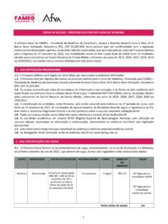
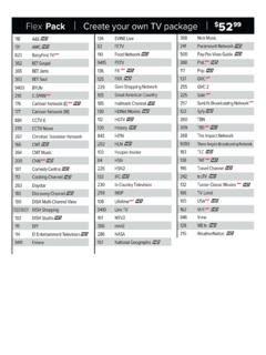
4 PT-JOY-G3 o PT-JOY-G3 Joystick Controller o Power Supply o User Manual (This Document) Ver. 8/19 Page4 Physical Descriptions . Top View of Joystick Controller . 1. Status / Menu LCD 2. Quick Camera Select 3. PTZ & Preset Control 4. Numeric Keypad 5. 4D Joystick 6. Focus Control Keys 7. Camera Image Control 1 2 3 5 4 6 7 Ver. 8/19 Page5 Back View of Joystick Controller . 1. Power LED Light (red) and Connection LED Light (green) 2. RS-232 Port (Not active on this model) 3. LAN Port (PoE enabled to power Joystick Controller from an switch) 4. RS-485 Port (Not active on this model) 5. 12 VDC Power Input Hardware Setup.
5 Power . Note: the Joystick Controller has a long boot-up procedure that can sometimes take up to 60 seconds to complete Standard Outlet o Using the supplied power adaptor connected the 12 VDC Power Input port Power over Ethernet (PoE) complying with the standard via the RJ45 port on the Joystick Controller Network . Note: The Joystick Controller will require the presence of a DHCP server on your network for initial configuration (IP address is set to DHCP by default) Connect a network cable from the RJ45 port on the Joystick Controller to your LAN NOTE: Failure to follow these sequences may result in no connection. 1 2 3 4 5 Ver. 8/19 Page6 Quick Start Basic Operation.
6 Initial setup for Joystick Controller on a LAN . Please ensure you have followed the steps on the previous pages for properly connecting your Joystick Controller to a proper power source (outlet or PoE) Please ensure you have followed the steps on the previous pages for properly connecting your Joystick Controller to a LAN that has a DHCP server present After everything is connected please wait for the Joystick Controller to complete its bootup cycle (up to 60 seconds) o Once the bootup cycle has completed the LCD panel will display the Joystick controllers current IP address as assigned by the local DHCP server on the LAN The Joystick Controller is now ready to have cameras added Adjusting the default language . If the Joystick Controller displays the incorrect language please follow the steps below to adjust to the desired language o Press the SET UP button to enter configuration mode o The second MENU displayed on the LCD is the language setting o Using the joysticks Pan, left / right, capability adjust the current setting to your desired language Example: English is displayed as EN o Press the ENTER button o Press the ESC button Ver.
7 8/19 Page7 Assigning a static IP to the Joystick Controller . Using the Joystick Controller . Note: When using the Joystick Controller with a static IP address you must ensure that the Joystick Controller is assigned to the same subnet as the IP cameras to be controlled Once you have completed the steps above to add your Joystick Controller to a LAN with a DHCP server you can assign a static IP for the Joystick Controller Press the SET UP button to enter configuration mode Use the Joystick (up / down) to navigate the menu on the LCD screen to menu item 03/05 or IP o Use the Joystick (right / left) to navigate the menu on the LCD screen to change the current setting of DHCP to STATIC o Press the Enter button o You will now be prompted to enter a static IP ADDRESS: using the alpha-numeric keypad Enter the static IP address using the.
8 Between octets as appropriate Example: Note: the Joystick Controller MUST be on the same subnet as the IP cameras to be controlled Press the Enter button o You will now be prompted to enter your static SUBNET MASK: using the alpha-numeric keypad Enter the subnet mask using the . between octets as appropriate Example: Press the Enter button o You will now be prompted to enter your static GATEWAY: , or Default Gateway, using the alpha-numeric keypad Enter the gateway using the . between octets as appropriate Example: Press the Enter button The Joystick Controller will now ask you to confirm that you want to apply these settings o Press the ENTER button to confirm and allow the device to reboot o Press the ESC button to cancel the entry of the static IP You will now see the static IP address displayed on the LCD once the Joystick Controller has completed its bootup cycle Ver.
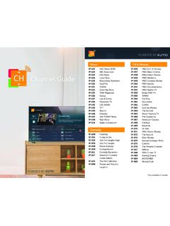
9 8/19 Page8 Assigning a static IP to the Joystick Controller (Cont.)_____ Note: You can also set the static IP address through the web interface after the Joystick has completed its boot up cycle. Select the Network Type dropdown and choose Static Address o Input the IP Address, Subnet Mask, & Gateway you would like set for the Joystick Upon saving the IP settings, you will be prompted to reboot the device to save IP settings Using the Joystick_____ ___ Adding Cameras . Please ensure you have followed the steps on the previous pages for properly connecting your Joystick Controller to a LAN Once the Joystick Controller has completed its bootup cycle press the SET UP button The SET UP button opens a menu on the LCD screen. Press the ENTER button to add a camera on setting 01/05 or Add Camera 1.
10 Set a Device ID for the corresponding camera 2. Input the camera s IP address into the Joystick including the . between octets. Example: IP = 3. Choose UDP or TCP control 4. Input control Port number PTZO ptics Default UDP Port #: 1259 PTZO ptics Default TCP Port #: 5678 You have now successfully added the cameras for IP control Ver. 8/19 Page9 Removing Cameras _____ __ . Note: You must delete a camera from the Joystick to free it s Device ID. Press the SET UP button and use the pan function of the Joystick to cycle over to the DEL DEVICE Press the ENTER key & enter the camera ID you would like to remove from the Joystick Confirm removing device by pressing ENTER You have now successfully removed a camera from the Joystick Using the web interface _____.