Transcription of Isolated AC-DC Converter with PFC
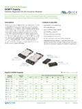
1 SNRTLCUSCUS PFM in a VIA PackageAC-DC Converter Isolated AC-DC Converter with PFCPFM4414xB6M48D0yzzPFM in a VIA Package Rev 1 of 24 08/2018 x x [ x x ]Part Ordering InformationProductFunctionPackage LengthPackageWidthPackageTypeInput VoltageRange RatioOutput Voltage (Range)Max Output PowerProduct GradeOption FieldPFM4414xB6M48D0yzzPFM =Power Factor ModuleLength in Inches x 10 Width in Inches x 10B = Board VIAV = Chassis VIAI nternal ReferenceC = 20 to 100 CT = 40 to 100 C00 = Chassis/Always On04 = Short Pin/Always On08 = Long Pin/Always OnFeatures & Benefits Universal input (85 264 VAC) 48 VOUT, regulated, Isolated SELV 92% typical efficiency Built-in EMI filtering Chassis-mount or board-mount packaging options Always-on, self-protecting Converter control architecture SELV Output Two temperature grades including operation to 40 C VIA Package Robust Mechanical Design Versatile thermal management capability Safe and reliable secondary-side energy storage High MTBF 140W/in3 power density 4414 package AC Input Front-End Module provides external rectification and transient protection (AIM sold separately)Typical Applications Small-cell base stations Telecom switching equipment LED lighting Industrial power systemsProduct DescriptionThe PFM in a VIA Package is a highly advanced 400W AC-DC Converter operating from a rectified universal AC input which delivers an Isolated and regulated Safety Extra Low Voltage (SELV) 48V secondary output.
2 This unique, ultra-low-profile module incorporates AC-DC conversion, integrated filtering and transient surge protection in a chassis-mount or PCB-mount form PFM enables a versatile two-sided thermal strategy which greatly simplifies thermal design combined with downstream Vicor DC-DC conversion components and regulators, the PFM allows the Power Design Engineer to employ a simple, low-profile design which will differentiate his end-system without compromising on cost or performance RatingsVIN = 85 264 VPOUT = up to 400 WVOUT = 48 VIOUT = with required companion component, AIM (see pages 2-3)PFM in a VIA Package Rev 2 of 24 08/2018 PFM4414xB6M48D0yzz 48 V 5 V 10 V 8 A Cool-Power ZVS Buck2 x Cool-Power ZVS Buck+_+_+_PFM4414+IN IN+OUT OUT48 V+++C1C2C3M1J185 - 264 VACI nlet+OUT OUTAIM1714M2F1 LNMOVT ypical PCB-Mount ApplicationsThe PCB terminal option allows mounting on an industry standard printed circuit board, with two different pin lengths.
3 Vicor offers a variety of downstream DC-DC converters driven by the 48V output of the PFM in a VIA package. The 48V output is usable directly by loads that are tolerant of the PFC line ripple, such as fans, motors, relays, and some types of lighting. Use downstream DC-DC point-of-load converters where more precise regulation is List for Typical PCB-Mount ApplicationsJ1 Qualtek 703W IEC 320-C14 Power InletF1 Littelfuse 8A 250 VAC 5 x 20mm holderM1 Vicor AIM AIM1714BB6MC7D5yzzM2 Vicor PFM PFM4414BB6M48D0yzzC1 Nichicon UVR1J472 MRD 4700 F 63V 22 x 50mm bent 90 x 2 pcsorCDE 380LX472M063K022 4700 F 63V 30 x 30mm snap x 2 pcs orSic Safco Cubisic LP A712121 10,000 F 63V 45 x 75 x 12mm rectangularor CDE MLPGE1571 6800 F 63V 45 x 50 x , 1 or TMOV20RP300E VARISTOR 10kA 300V 250 J 20mm PFM in a VIA Package Rev 3 of 24 08/2018 PFM4414xB6M48D0yzzPFM4414+IN IN+OUT OUTFanRelaysCoin BoxControllerDispensors48V1688C1C2C3J185 - 264 VACI nletM1 AIM1714F1M2+OUT OUTLNMOVT ypical Chassis-Mount ApplicationsThe PFM in a VIA package is available in chassis-mount option, saving the cost of a PCB and allowing access to both sides of the power supply for cooling.
4 The parts list below minimizes the number of interconnects required between necessary components, and selects components with terminals traditionally used for point-to-point chassis List for Typical Chassis-Mount ApplicationsJ1 Qualtek 719W or 723W IEC 320-C14 Power InletF1 Littelfuse 8A 250 VAC 5 x 20mm in a J1, or separate fuse holderM1 Vicor AIM AIM1714VB6MC7D5y00M2 Vicor PFM PFM4414VB6M48D0y00C1 UCC E32D630 HPN103MA67M 10,000 F, 63V , 35 x 67mm screw terminalorKemet ALS30A103DE063, 10,000 F 63V 36 x 84mm screw terminalMOVL ittelfuse TMOV20RP300E VARISTOR 10kA 300V 250 J 20mm PFM in a VIA Package Rev 4 of 24 08/2018 PFM4414xB6M48D0yzz124+IN+OUTTOP VIEWPFM4414 VIA - Chassis Mount - Terminals Up3 OUT IN213 IN OUTTOP VIEWPFM4414 VIA - PCB Mount - Pins Down4+OUT+INPin ConfigurationPin DescriptionsPlease note that these Pin drawings are not to NumberSignal NameTypeFunction1+ININPUT POWERP ositive input power terminal2 ININPUT POWER RETURNN egative input power terminal3+OUTOUTPUT POWERP ositive output power terminal4 OUTOUTPUT POWER RETURNN egative output power terminalPFM in a VIA Package Rev 5 of 24 08/2018 PFM4414xB6M48D0yzzOutput Current (A) Case Temperature ( C)CurrentPower0 100 200 300 400 500 -60 -40 -20 0 20 40 60 80 100 Output Power (W)Safe operating areaAbsolute Maximum RatingsThe absolute maximum ratings below are stress ratings only.
5 Operation at or beyond these maximum ratings can cause permanent damage to the Voltage +IN to IN1ms max0600 VPKI nput Voltage (+IN to IN)Continuous, Rectified0275 VRMSO utput Voltage (+OUT to OUT) Torque4 mounting, 2 input, 2 output 4 [ ] [ ]Operating Internal TemperatureT-Grade 40125 CStorage TemperatureT-Grade 65125 CDielectric Withstand *See note belowInput-CaseBasic Insulation2121 VDCI nput-OutputReinforced Insulation (Internal ChiP tested at 4242 VDC prior to assembly.)2121 VDCO utput-CaseFunctional Insulation707 VDC* Please see Dielectric Withstand section. See page in a VIA Package Rev 6 of 24 08/2018 PFM4414xB6M48D0yzzElectrical SpecificationsSpecifications apply over all line and load conditions, 50Hz and 60Hz line frequencies, TINT = 25 C, unless otherwise noted; boldface specifications apply over the temperature range of the specified product grade. COUT is 10,000 F 20% unless otherwise / NotesMinTypMaxUnitPower Input SpecificationInput Voltage Range, Continuous OperationVIN85264 VRMSI nput Voltage Range, Transient, Non-Operational (Peak)VIN1ms600 VInput Voltage Cell ReconfigurationLow-to-High ThresholdVIN-CR+145148 VRMSI nput Voltage Cell ReconfigurationHigh-to-Low ThresholdVIN-CR 132135 VRMSI nput Current (Peak)IINRPSee Figure 8, start-up waveforms12 ASource Line Frequency Rangefline4763 HzPower FactorPFInput power > Inductance, MaximumLIND ifferential mode inductance, common-mode inductance may be higher.
6 See section Source Inductance Considerations on page Capacitance, MaximumCINA fter AIM , between +IN and FNo Load SpecificationInput Power No Load, MaximumPNL7 WPower Output SpecificationOutput Voltage Set PointVOUTVIN = 230 VRMS, 100% load464850 VOutput voltage, No LoadVOUT-NLOver all operating steady state line conditions. Wider tolerance valid up to 50W output due to line cycle Voltage Range (Transient)VOUTNon-faulting abnormal line and load transient PowerPOUTSee SOA on Page 5400 WEfficiency VIN = 230V, full load, exclusive of AIM < VIN < 264V, full load, exclusive of AIM losses90%85V < VIN < 264V, 75% load,exclusive of AIM losses90%Output Voltage Ripple,Switching FrequencyVOUT-PP-HFOver all operating steady-state line and load conditions, 20 MHz BW, measured at output, Figure 52002000mVOutput Voltage RippleLine FrequencyVOUT-PP-LFOver all operating steady-state line and load conditions, 20 MHz Capacitance (External)COUT-EXTA llows for 20% capacitor tolerance680015000 FOutput Turn-On DelayTONFrom VIN applied5001000msStart-Up Set-Point Aquisition TimeTSSFull load5001000msCell Reconfiguration Response TimeTCRFull Deviation (Transient)
7 %VOUT-TRANS TimeTTRANS300600msLine Regulation%VOUT-LINEFull load3%Load Regulation%VOUT-LOAD10% to 100% load3%Output Current (Continuous) Current (Transient)IOUT-PK20ms duration, average power POUT, in a VIA Package Rev 7 of 24 08/2018 PFM4414xB6M48D0yzzElectrical Specifications (Cont.)Specifications apply over all line and load conditions, 50Hz and 60Hz line frequencies, TINT = 25 C, unless otherwise noted; boldface specifications apply over the temperature range of the specified product grade. COUT is 10,000 F 20% unless otherwise / NotesMinTypMaxUnitPowertrain ProtectionsInput Undervoltage Turn-OnVIN-UVLO+See Timing Diagram7483 VRMSI nput Undervoltage Turn-OffVIN-UVLO 6571 VRMSI nput Overvoltage Turn-OnVIN-OVLO See Timing Diagram265270 VRMSI nput Overvoltage Turn-OffVIN-OVLO+273287 VRMSO utput Overvoltage ThresholdVOUT-OVLO+Instantaneous, latched shutdown586164 VUpper Start / Restart Temperature Threshold (Case)TCASE-OTP 100 COvertemperature ShutdownThreshold (Internal)TINT-OTP+125 COvertemperature Shutdown Threshold (Case)
8 TCASE-OTP+110 COvercurrent Blanking TimeTOCB ased on line frequency400460550msInput Overvoltage Response TimeTPOVP40msInput Undervoltage Response TimeTUVLOB ased on line frequency200msOutput Overvoltage Response TimeTSOVPP owertrain on30msShort Circuit Response TimeTSCP owertrain on, operational state270 sFault Retry Delay TimeTOFFSee Timing Diagram10sOutput Power LimitPPROT50% overload for 20ms typ allowed400 WPFM in a VIA Package Rev 8 of 24 08/2018 PFM4414xB6M48D0yzzTiming DiagramVIN-RMSENVOUTILOADVIN-OVLO+1 Input Power On & UV Turn-on3 Full Load Applied4EN Forced Low5 ENHigh6 RangeChangeLO to HI9 RangeChangeHI to LO7 InputOVTurn-off8 Input OV Turn-on10 LoadDump11 Load Step12 Input Power Off & UV Turn-offInputOutputtCRtONVIN-UVLO+ 30 VRMS210%Load AppliedtCRtTRANS (2 places)VIN-OVLO-VIN-UVLO-VIN-CR+VIN-CR-V OUT-NLVOUTtONtONtPOVPtUVLOtEN-DIStSStSSP FM in a VIA Package Rev 9 of 24 08/2018 PFM4414xB6M48D0yzzTiming Diagram (Cont.)VIN-RMSVOUTILOADtONVIN-UVLO+tOCtO FF+tONtOFF+tONtOC tOFF+tONVOUT-OVLO+tSOVPtONtSSVIN-UVLO-tS CtOFF+tONtOFF+tONENtOC))))))))))))13 Input Power ON & UV Turn-on14 Output OC Fault15 Output OC Recovery16 Output OVP Fault17 Toggle EN (Output OVP Recovery)18 Output OVPF ault19 Recycle Input Power (Output OVP Recovery)20 Output SCFault21 OutputSC Recovery22OT Fault&Recovery23 Line Drop-Out24 Input Power Off & UV Turn-offInputOutputtONVIN-UVLO+))))))))) )))**PFM in a VIA Package Rev 10 of 24 08/2018 PFM4414xB6M48D0yzzApplication CharacteristicsEfficiency (%) Input Line 1 Full-load efficiency vs.
9 Line voltageNo Load Power Dissipation (W) Input Line C Figure 2 Typical no-load power dissipation vs. VIN , module enabledCurrent (mA) 230V, 50Hz1/3x EN61000-3-2, Class A EN61000-3-2, Class D 0 100 200 300 400 500 600 700 800 1 3 5 7 9 11 13 15 17 19 21 23 25 27 29 31 33 35 37 39 Figure 3 Typical input current harmonics, full load vs. VIN using typical applications circuit on pages 2 & 3 Figure 5 Typical switching frequency output voltage ripple waveform, TCASE = 30 C, VIN = 230V, IOUT = , no external ceramic capacitance, 20 MHz BWPower Factor Output Power (W)120V/60Hz 230V/50Hz 100V/50 0 100 200 300 400 Figure 4 Typical power factor vs. VIN and IOUT using typical applications circuit on pages 2 & 3 Figure 6 Typical line frequency output voltage ripple waveform, TCASE = 30 C, VIN = 230V, IOUT = , COUT = 10,000 F. 20 MHz BWPFM in a VIA Package Rev 11 of 24 08/2018 PFM4414xB6M48D0yzzFigure 12 Typical line current waveform, VIN = 120V, 60Hz IOUT = , COUT = 10,000 FFigure 11 Line drop out, 90 phase, VIN = 230V, IOUT = , COUT = 10,000 FFigure 10 Line drop out, 230V 50Hz, 0 phase, IOUT = , COUT = 10,000 FFigure 9 230V, 120V range change transient response, IOUT = , COUT = 10,000 FFigure 7 Typical output voltage transient response, TCASE = 30 C, VIN = 230V, IOUT = , COUT = 10,000 FFigure 8 Typical start-up waveform, application of VIN , IOUT = , COUT = 10,000 FApplication Characteristics (Cont.)
10 PFM in a VIA Package Rev 12 of 24 08/2018 PFM4414xB6M48D0yzzLoad Current (A)Efficiency (%)Power Dissipation (W)85V115V230VV :IN85V115V230 VEffP Diss101520253035404550788082848688909294 0123456789 Figure 17 VIN to VOUT efficiency and power dissipation vs. VIN and IOUT , TCASE = 80 C150 kHz30 MHzTrd55022 REDSGL2 AVUnitdBV 1 QPResBW9 kHzMeas T20 msDetQPAtt 20 dBINPUT 2017 14:251 MHz10 MHz 30 40 50 60 70 80 90 20 10022 QPB22 AVBDate: 14:25:07 Figure 13 Typical EMI spectrum, peak scan, 90% load, 115 VIN, COUT = 10,000 F using typical chassis-mount application circuitApplication Characteristics (Cont.)150 kHz30 MHzTrd55022 REDSGL2 AVUnitdBV1 QPResBW 9 kHzMeas T 20 msDetQPAtt20 dBINPUT 2017 12:291 MHz10 MHz 30 40 50 60 70 80 90 20 10022 QPB22 AVBDate: 12:29:36 Figure 14 Typical EMI spectrum, peak scan, 90% load, 230 VIN, COUT = 10,000 F using typical chassis-mount application circuitLoad Current (A)Efficiency (%)Power Dissipation (W)85V115V230VV :IN85V115V230 VEffP Diss051015202530354078808284868890929401 23456789 Figure 15 VIN to VOUT efficiency and power dissipation vs.