Transcription of Isolated Fixed-Ratio DC-DC Converter - Vicor Corporation
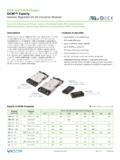
1 BCM Bus ConverterBCM6123xD1E13A3yzzIsolated Fixed-Ratio DC-DC ConverterSNRTLCUSCUS BCM Bus Converter Rev 1 of 30 07/2018 Features & Benefits Up to 125A continuous secondary current Up to 2208W/in3 power density peak efficiency 4,242 VDC isolation Parallel operation for multi-kW arrays OV, OC, UV, short circuit and thermal protection BCM6123 through-hole ChiP package x x [ x x ] PMBus management interface [a]Typical Applications 380 VDC Power Distribution High-End Computing Systems Automated Test Equipment Industrial Systems High-Density Power Supplies Communications Systems TransportationProduct DescriptionThe BCM6123xD1E13A3yzz is a high-efficiency Bus Converter , operating from a 260 to 410 VDC primary bus to deliver an Isolated , ratiometric secondary voltage from to BCM6123xD1E13A3yzz offers low noise, fast transient response, and industry leading efficiency and power density.
2 In addition, it provides an AC impedance beyond the bandwidth of most downstream regulators, allowing input capacitance normally located at the input of a PoL regulator to be located at the primary side of the BCM. With a primary to secondary K factor of 1/32, that capacitance value can be reduced by a factor of 1024x, resulting in savings of board area, material and total system the thermal and density benefits of Vicor ChiP packaging technology, the BCM offers flexible thermal management options with very low top and bottom side thermal impedances. Thermally-adept ChiP-based power components enable customers to achieve low cost power system solutions with previously unattainable system size, weight and efficiency attributes quickly and product can operate in the reverse direction, at full rated current, after being previously started in the forward RatingsVPRI = 384V (260 410V)ISEC = up to 125 AVSEC = 12V ( )(no load)
3 K = 1/32[a]When used with D44TL1A0 and I13TL1A0 BCM Bus Converter Rev 2 of 30 07/2018 BCM6123xD1E13A3yzzBCMVAUXEN+VPRI VPRI+VSEC VSECSW1 VPRI enable/disableswitchF1 ISOLATION BOUNDARYPRIMARYSECONDARYGNDCPRITMPoLTypi cal ApplicationsBCM6123xD1E13A3y00 at point-of-loadBCMSER-INEN+VPRI VPRI+VSEC VSEC enable/disableswitchFUSEISOLATION BOUNDARYPRIMARYSECONDARYSER-OUT CI_BCM_ELEC SOURCE_RTNVPRIPRI_OUT_APRI_COMSEC_IN_ASE C_OUT_CDigital IsolatorI13TL1A0 VDDBVDDTXDRXDPMBusSGNDtHost CSEC_COMPMBusSGND+ VEXTPRI_IN_CSEC_IN_BPRI_OUT_BNCSGNDSGNDS GNDSER-OUTSER-INSER-INSER-OUTPoLDigitalS upervisorD44TL1A0 BCM6123xD1E13A3y01 at point-of-loadBCM Bus Converter Rev 3 of 30 07/2018 BCM6123xD1E13A3yzzTypical Applications (Cont.)+VPRI+VSECTM / SER-OUTENISOLATION BOUNDARYVAUX / SER-IN VPRI VSECLOAD3-Phase AIMBCM6123 ChiP + L1L2L33-phase AC to point-of-load (3-phase AIM + BCM6123xD1E13A3yzz)BCM Bus Converter Rev 4 of 30 07/2018 BCM6123xD1E13A3yzz[b] For proper operation an external low impedance connection must be made between listed VSEC1 and VSEC2 H +VPRI+VSECTOP VIEWBCM6123 ChiP I VSEC1 VSEC1+VSEC+VSEC VSEC1+VSEC VSEC1+VPRIJ+VPRIK+VPRILA B C D E F G H I J K L +VSEC VSEC2 VSEC2+VSEC+VSEC VSEC2+VSEC VSEC2 VPRITM/SER-OUTENVAUX/SER-INPin ConfigurationPin DescriptionsPower PinsPin NumberSignal NameTypeFunctionI1, J1, K1, L1+VPRIPRIMARY POWERP ositive primary transformer power terminalL 2 VPRIPRIMARY POWER RETURNN egative primary transformer power terminalA1, D1, E1, H1, A 2, D 2, E 2, H 2+VSECSECONDARY POWERP ositive secondary transformer power terminalB1, C1, F1, G1B 2, C 2, F 2, G 2 VSEC [b]SECONDARY POWER RETURNN egative secondary transformer power terminalAnalog Control Signal PinsPin NumberSignal NameTypeFunctionI 2 TMOUTPUTT emperature Monitor.
4 Primary side referenced signalsJ 2 ENINPUTE nables and disables power supply; primary side referenced signalsK 2 VAUXOUTPUTA uxiliary Voltage Source; primary side referenced signalsPMBus Control Signal PinsPin NumberSignal NameTypeFunctionI 2 SER-OUTOUTPUTUART transmit pin; Primary side referenced signalsJ 2 ENINPUTE nables and disables power supply; Primary side referenced signalsK 2 SER-ININPUTUART receive pin; Primary side referenced signalsBCM Bus Converter Rev 5 of 30 07/2018 BCM6123xD1E13A3yzzPart Ordering InformationStandard ModelsProduct FunctionPackage SizePackage MountingMax Primary Input VoltageRange IdentifierMax Secondary VoltageSecondaryOutput CurrentTemperature GradeOptionBCM6123xD1E13A3yzzBus Converter Module61 = L 23 = WT = TH410V 260 410V13 VNo Load125AT = 40 to 125 CM = 55 to 125 C 00 = Analog Ctrl01 = PMBus Ctrl0R = Reversible Analog Ctrl0P = Reversible PMBus CtrlProduct FunctionPackage SizePackage MountingMax Primary Input VoltageRange IdentifierMax Secondary VoltageSecondaryOutput CurrentTemperature GradeOptionBCM6123TD1E13A3T00 BCM6123TD1E13A3T01 BCM6123TD1E13A3T0 RBCM6123TD1E13A3T0 PAll products shipped in JEDEC standard high profile ( thick) trays (JEDEC Publication 95, Design Guide ).
5 Absolute Maximum RatingsThe absolute maximum ratings below are stress ratings only. Operation at or beyond these maximum ratings can cause permanent damage to the +VPRI_DC to VPRI_DC 1480 VVPRI_DC or VSEC_DC Slew Rate (Operational)1V/ s+VSEC_DC to VSEC_DC 115 VTM/SER-OUT to VPRI_DC to to Bus Converter Rev 6 of 30 07/2018 BCM6123xD1E13A3yzzAttributeSymbolConditi ons / NotesMinTypMaxUnitGeneral Powertrain PRIMARY to SECONDARY Specification (Forward Direction)Primary Input Voltage Range (Continuous)VPRI_DC260410 VVPRI ControllerV C_ACTIVEVPRI_DC voltage where C is initialized, ( , VAUX = Low, powertrain inactive)130 VPRI to SEC Input Quiescent CurrentIPRI_QDisabled, EN Low, VPRI_DC = 384V2mATINTERNAL 100 C4 PRI to SEC No-Load Power Dissipation PPRI_NLVPRI_DC = 384V, TINTERNAL = 25 C1117 WVPRI_DC = = 260 410V, TINTERNAL = 25 C19 VPRI_DC = 260 410V27 PRI to SEC Inrush Current PeakIPRI_INR_PKVPRI_DC = 410V, CSEC_EXT = 1000 F, RLOAD_SEC = 50% of full-load current10 ATINTERNAL 100 C15DC Primary Input CurrentIPRI_IN_DCAt ISEC_OUT_DC = 125A, TINTERNAL 100 RatioKPrimary to secondary, K = VSEC_DC / VPRI_DC, at no load1/32V/VSecondary Output Current(Continuous)ISEC_OUT_DC125 ASecondary Output Current (Pulsed)ISEC_OUT_PULSE10ms pulse, 25% duty cycle, ISEC_OUT_AVG 50% of rated ISEC_OUT_DC167 ASecondary Output Power(Continuous)PSEC_OUT_DCSpecified at VPRI_DC = 410V1500 WSecondary Output Power(Pulsed)PSEC_OUT_PULSES pecified at VPRI_DC = 410V.
6 10ms pulse, 25% duty cycle, PSEC_AVG 50% of rated PSEC_OUT_DC2000 WPRI to SEC Efficiency (Ambient) AMBVPRI_DC = 384V, ISEC_OUT_DC = = 260 410V, ISEC_OUT_DC = = 384V, ISEC_OUT_DC = to SEC Efficiency (Hot) HOTVPRI_DC = 384V, ISEC_OUT_DC = to SEC Efficiency (Over Load Range) 20%25A < ISEC_OUT_DC < 125A90%PRI to SEC Output ResistanceRSEC_COLDVPRI_DC = 384V, ISEC_OUT_DC = 125A, TINTERNAL = 40 RSEC_AMBVPRI_DC = 384V, ISEC_OUT_DC = = 384V, ISEC_OUT_DC = 125A, TINTERNAL = 100 FrequencyFSWF requency of the output voltage ripple = 2x Output Voltage RippleVSEC_OUT_PPCSEC_EXT = 0 F, ISEC_OUT_DC = 125A, VPRI_DC = 384V, 20 MHz BW195mVTINTERNAL 100 C250 Primary Input Leads Inductance (Parasitic)LPRI_IN_LEADSF requency (double switching frequency), simulated lead model7nHSecondary Output Leads Inductance (Parasitic)LSEC_OUT_LEADSF requency (double switching frequency), simulated lead Input Series Inductance(Internal)LIN_INTR educes the need for input decoupling inductance in BCM HElectrical SpecificationsSpecifications apply over all line and load conditions, unless otherwise noted; boldface specifications apply over the temperature range of 40 C TINTERNAL 125 C (T-Grade).
7 All other specifications are at TINTERNAL = 25 C unless otherwise Bus Converter Rev 7 of 30 07/2018 BCM6123xD1E13A3yzzElectrical Specifications (Cont.)Specifications apply over all line and load conditions, unless otherwise noted; boldface specifications apply over the temperature range of 40 C TINTERNAL 125 C (T-Grade). All other specifications are at TINTERNAL = 25 C unless otherwise / NotesMinTypMaxUnitGeneral Powertrain PRIMARY to SECONDARY Specification (Forward Direction) Primary Capacitance (Internal)CPRI_INTE ffective value at FEffective Secondary Capacitance (Internal)CSEC_INTE ffective value at 12 VSEC_DC208 FRated Secondary Output Capacitance (External)CSEC_OUT_EXTE xcessive capacitance may drive module into short-circuit protection1000 FRated Secondary Output Capacitance (External), Parallel Array OperationCSEC_OUT_AEXTCSEC_OUT_AEXT Max = N CSEC_OUT_EXT MAX, where N = the number of units in parallelPowertrain Protection PRIMARY to SECONDARY (Forward Direction)Auto Restart TimetAUTO_RESTARTS tart up into a persistent fault condition.
8 Non-latching fault detection given VPRI_DC > VPRI_UVLO+ Overvoltage Lockout ThresholdVPRI_OVLO+ Overvoltage Recovery ThresholdVPRI_OVLO 410424440 VPrimary Overvoltage Lockout Overvoltage Lockout Response TimetPRI_OVLO100 sSecondary Soft-Start TimetSEC_SOFT-STARTFrom powertrain active; fast current limit protection disabled during soft start1msSecondary Output Overcurrent Trip ThresholdISEC_OUT_OCP145170210 ASecondary Output Overcurrent Response Time ConstanttSEC_OUT_OCPE ffective internal RC filter3msSecondary Output Short-Circuit Protection Trip ThresholdISEC_OUT_SCP187 ASecondary Output Short-Circuit Protection Response TimetSEC_OUT_SCP1 sOvertemperature Shut-Down ThresholdtOTP+Temperature sensor located inside controller IC125 CBCM Bus Converter Rev 8 of 30 07/2018 BCM6123xD1E13A3yzzElectrical Specifications (Cont.)Specifications apply over all line and load conditions, unless otherwise noted; boldface specifications apply over the temperature range of 40 C TINTERNAL 125 C (T-Grade).
9 All other specifications are at TINTERNAL = 25 C unless otherwise / NotesMinTypMaxUnitPowertrain Supervisory Limits PRIMARY to SECONDARY (Forward Direction)Primary Overvoltage Lockout ThresholdVPRI_OVLO+ Overvoltage Recovery ThresholdVPRI_OVLO 410424440 VPrimary Overvoltage Lockout Overvoltage Lockout Response TimetPRI_OVLO100 sPrimary Undervoltage Lockout ThresholdVPRI_UVLO 195221250 VPrimary Undervoltage Recovery ThresholdVPRI_UVLO+225243255 VPrimary Undervoltage Lockout HysteresisVPRI_UVLO_HYST15 VPrimary Undervoltage Lockout Response TimetPRI_UVLO100 sPrimary-to-Secondary Start-Up DelaytPRI_TO_SEC_DELAYFrom VPRI_DC = VPRI_UVLO+ to powertrain active, EN floating ( , one-time start-up delay from application of VPRI_DC to VSEC_DC)20msSecondary Output Overcurrent Trip ThresholdISEC_OUT_OCP145170210 ASecondary Output Overcurrent Response Time ConstanttSEC_OUT_OCPE ffective internal RC filter3msOvertemperature Shut-Down ThresholdtOTP+Temperature sensor located inside controller IC125 COvertemperature Recovery ThresholdtOTP 105110115 CUndertemperature Shut-Down ThresholdtUTPT emperature sensor located inside controller IC; Protection not available for M-Grade units.
10 45 CUndertemperature Restart TimetUTP_RESTARTS tart up into a persistent fault condition. Non-latching fault detection given VPRI_DC > VPRI_UVLO+ 3sBCM Bus Converter Rev 9 of 30 07/2018 BCM6123xD1E13A3yzzAttributeSymbolConditi ons / NotesMinTypMaxUnitGeneral Powertrain SECONDARY to PRIMARY Specification (Reverse Direction)Secondary Input Voltage Range (Continuous) to PRI No-Load Power Dissipation PSEC_NLVSEC_DC = 12V, TINTERNAL = 25 C1117 WVSEC_DC = = , TINTERNAL = 25 C19 VSEC_DC = Secondary Input CurrentISEC_IN_DCAt IPRI_DC = , TINTERNAL 100 C127 APrimary Output Power (Continuous)PPRI_OUT_DCSpecified at VSEC_DC = Output Power (Pulsed)PPRI_OUT_PULSES pecified at VSEC_DC = ; 10ms pulse,25% duty cycle, PPRI_AVG 50% of rated PPRI_OUT_DC2000 WPrimary Output Current (Continuous) Output Current (Pulsed)IPRI_OUT_PULSE10ms pulse, 25% duty cycle, IPRI_OUT_AVG 50% of rated to PRI Efficiency (Ambient) AMBVSEC_DC = 12V, IPRI_OUT_DC = = , IPRI_OUT_DC= = 12V, IPRI_OUT_DC = to PRI Efficiency (Hot) HOTVSEC_DC = 12V, IPRI_OUT_DC = to PRI Efficiency (Over Load Range) 20% < IPRI_OUT_DC < to PRI Output ResistanceRPRI_COLDVSEC_DC = 12V, IPRI_OUT_DC = , TINTERNAL = 40 C210024002700m RPRI_AMBVSEC_DC = 12V, IPRI_OUT_DC = = 12V, IPRI_OUT_DC = , TINTERNAL = 100 C290031503400 Primary Output Voltage RippleVPRI_OUT_PPCPRI_OUT_EXT = 0 F, IPRI_OUT_DC = , VSEC_DC = 12V, 20 MHz BW6250mVTINTERNAL 100 C9600 Electrical Specifications (Cont.)
