Transcription of IVT vs. V‐Roller - PBC Linear
1 IVT vs. V Roller A Technical Comparison Between integral v technology (IVT) and V Roller System with Steel Rails Kevin Bischel Sr. System Design Engineer 7/8/2010 Historically, one of the more common Linear guidance systems used has been bearing blocks containing re circulating ball bearings running on profiled steel rails that are fastened to a structure. In recent years, PBC Linear has introduced another type of Linear guidance system called integral v technology (IVT). In these systems, cam rollers of v profile run on steel raceways that are mechanically fixed into a structural aluminum component to form a unified rail component.
2 White Paper: IVT vs. V Roller System Page 1 of 10 Introduction Historically, one of the more commonly used Linear guidance systems has been cam rollers of v profile running on separate steel rails fastened to a structure. In recent years, PBC Linear has introduced another type of Linear guidance system called integral v technology (IVT). In these systems cam rollers of v profile run on steel raceways that are mechanically fixed into a structural aluminum component to form a unified rail component. The purpose of this paper is to describe the two systems, some of their important features and differentiators, and provide a relative cost comparison given a common application.
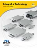
3 Overview of V rollers with Steel Rail Introduced in the early 1970 s, these products consist of cam rollers with v profiles that run on matching steel rails as shown in Two disadvantages of such Linear guidance systems are: Fig. 1: V roller rails and steel rail Fig. 2: V roller rails often require many fasteners1. The rails must be fastened with multiple fasteners to the supporting structure. The standard holes are spaced at 2 inch (51mm), 3 inch (76mm), or 4 inch (102mm) intervals depending on the rail size.
4 The fasteners add labor cost, assembly time, and increase the possibility of assembly error or fastener failure. 2. The accuracy of the system is dependent on the flatness, straightness and parallelism of the supporting structure. Most v roller applications do not require high accuracy. It is adequate in many applications to attach the rails directly to cold finished or extruded material. Rails are supplied with shoulders to mount against the square edges of plates or bars. For designs requiring accuracy levels of .005inch/ft (.)
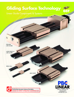
5 13mm/300mm) and better, the mounting surfaces must be prepared appropriately flat, straight, and parallel Reference edge assemblies should also be used. Greater accuracy can be obtained by fastening the rails to a plate or bar that has been prepared by milling or grinding the mounting surfaces flat and parallel. Fig. 3: The accuracy of v roller rails is largely dependent on the flatness, straightness and parallelism of the surfaces to which they mount. In the diagram above, surface A should be flat; surfaces B and C should be flat and parallel.
6 One also wants the support structure to be straight with minimal twist or camber. White Paper: IVT vs. V Roller System Page 2 of 10 The following table contains dimensional tolerances that one can generally expect for extruded aluminum. 1 Camber (Bar) Wall Thickness Per Length to in (to ) .0125 in/ft (1mm/m) over .094 in (over ) .05 in/ft (4mm/m) Twist (Bar) Widest Dimension Per Length Maximum to in (40mm) 1 / ft (3 / m) 7 (40 75mm) 1/2 / ft ( / m) 5 over (75mm) 1/4 / ft (3/4 / m) 3 Flatness (Bar) WIDTH Up ( ) ( ) to to to Minimum thickness of metal forming the surface ( ) ( ) ( ) to.
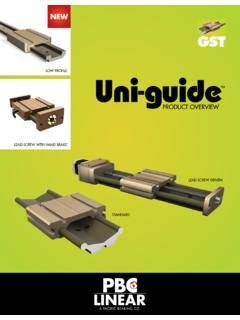
7 124in ( ) .004in (.10mm) .006in (.15mm) .010in (.25mm) .125 .187in ( ) .004in (.10mm) .006in (.15mm) .008in (.20mm) .188 .249in ( ) .004in (.10mm) .006in (.15mm) .008in (.20mm) .250 .374in ( ) .004in (.10mm) .006in (.15mm) .006in (.15mm) .375 .499in ( ) .004in (.10mm) .004in (.10mm) .006in (.15mm) .500 .749in ( ) .004in (.10mm) .004in (.10mm) .006in (.15mm) .750 .999in ( ) .004in (.10mm) .004in (.10mm) .006in (.15mm) Fig. 4: lllustration of camber, twist and flatness. When preparing mounting faces by machining, the amounts of deviation from flatness one can generally expect are within: Face Milling2: in/ft ( ) Surface Grinding2: in/ft (.)
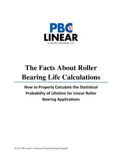
8 08mm/m) White Paper: IVT vs. V Roller System Page 3 of 10 The fasteners along the length of the v rails allow some tolerance variations that occur in long wavelengths to be removed during assembly. This is done by shifting and aligning the v rails within the clearances of the fastener holes and tightening the fasteners. But tolerance variations that occur in short wavelengths cannot be adjusted out during assembly because of the stiffness of the v rail and the spacing of the fasteners. Fig. 5: Stack up of tolerances affects the location tolerances of steel v rail assemblies Before PBC Linear developed the IVT system, manufacturers tried several methods to improve the dimensional tolerances of the steel rail systems and to provide a rail assembly that did not require fasteners.
9 One method tried was to insert steel v rails directly into extruded pockets in an aluminum extrusion. However, the dimensional tolerances of such rail assemblies depended on the as extruded tolerances of the aluminum extrusion which are unacceptably high for many applications. Fig. 6: Steel v rails inserted into extruded pockets in an aluminum structure. Another method is to have aluminum fingers extruded within the pockets. The fingers are designed to deform and support the steel v rails when they were pressed in. Rollers are used during the assembly process to insert the steel v rails a controlled amount.
10 The location tolerances for the steel v rails were improved, but location tolerances are still dependent on extrusion tolerances such as twist and flatness. The stiffness of the steel rails themselves still prevents short wavelength dimensional variations from being removed. White Paper: IVT vs. V Roller System Page 4 of 10 Fig. 7: Steel v rails inserted in extruded or machined pockets containing fingers in an aluminum structure. To reduce the effect of the extrusion tolerances on the final rail tolerances, the pockets and fingers in the aluminum structure can be machined rather than extruded.