Transcription of Joint Deflection For - National Pipe And Plastic
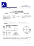
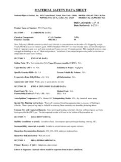
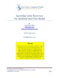
1 Joint Deflection For: AWWA Pressure Pipe C900 & C905. The Joint Deflection of National 's AWWA pressure pipe may be achieved by following the recommended procedure and limits, as defined: 1. Keeping pipe length in straight alignment with the previously laid length, insert spigot end into the gasketed bell until the reference mark is flush with the leading edge of the bell lip. 2. Move to opposite end of the pipe and manually offset the pipe to the recommended offset. A block and bar may be used on large/heavier diameter pipe to provide continually controlled movement. Never use excavation equipment to obtain offset. 3. Partially backfill installed pipe length to secure placements. 4. If additional Deflection is required, proceed from sequence 1, on next pipe length. Caution: Over insertion of spigot end and/or exceeding the recommended offset may create material stress at Joint assembly.
2 A B R*. Nominal Size Maximum Offset Angle of Offset Radius of Curve (in.) (in.) (ft.). 4 12 4 1 1146. 14+ 4 1 1146. Radius of curve determined for 20 ft. lay length. Caution: The use of PVC fitting or longitudinal bending of pipe lengths may be a more appropriate method for linear redirection of installation where unstable soil conditions exist. R. R. A B. Updated 12/13.