Transcription of K0903V1 2/06 Rev. B ADEMCO 6160RF - Honeywell
1 K0903V1 2/06 Rev. B ADEMCO 6160 RFKeypad/TransceiverInstallation and Setup Guide GENERAL INFORMATION The ADEMCO 6160RF keypad/transceiver is a combination unit that combines the functions of the following devices: 6160 Alphanumeric Addressable Keypad 5881H RF Receiver 5800TM Transmitter Module The 6160RF Keypad/Transceiver may be used on any control panel that supports 5800 series wireless devices ( , vista -10P, vista -15P, vista -20P). FEATURES Supports wireless key transmitters ( ; 5804) and bi-directional transmitters ( ; 5804BD, 5828/5828V). Supports wireless keys with high-security (encryption) capability ( ; 5804E).
2 Provides a nominal range of 200 feet' for RF transmitters (some transmitters have a shorter range). Supports RF jam detection when the receiver is enabled. Capable of sending status signals (Armed, Ready, etc.) to bi-directional units such as 5804BD, 5804 BDV and 5828/5828V. UUUULLLL The following 5800 series transmitters are not intended for use in UL installations: 5802, 5804, 5804BD, 5804 BDV, 5804E, 5814, 5816 TEMP, 5819, 5819 BRS, 5819 WHS, 5828/5828V and 5850. INSTALLING THE 6160RF Locate the 6160RF in an area and at a height where it is convenient for user operation. The 6160RF must be at least 10 ft from the control panel to ensure proper operation of the RF receiver.
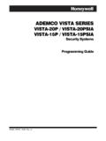
3 Mounting and Wiring The 6160RF has terminal blocks for connection to power and data wires. Removing the keypad s case back provides access to the terminal blocks. The 6160RF can be surface mounted directly to walls, or to a single- or double-gang electrical box. Follow these steps to mount and wire the keypad: 1. Push the two case release snaps at the bottom of the keypad with the blade of a medium screwdriver (this will push in the release snap), then pull that side of the case back away. Insert the screwdriver in the side of the keypad (between the front and back case) and gently twist to release the side locking tab. Repeat for the other side.
4 Refer to Figure 1 for location of the case back release snaps and locking tabs. ARMEDREADYMOUNTINGRELEASESNAPSNOTE:TO REMOVE REAR COVERPUSH IN THE TWO MOUNTINGSNAPS LOCATED ALONG THE BOTTOM OF THE KEYPADAND LIFT COVER B Figure 1. Removing the Case Back 2. Pass the wiring from the control panel through the opening in the case back. (see the control panel s instructions for proper run lengths.) a. If surface wiring is being used, wiring may be routed through the top or the bottom left-side breakout in the case back. The breakouts must be punched out using a screwdriver before mounting the case back. b. If desired, wires may be strain-relieved to the wire tie point on the inside of the case back with a tie wrap (not supplied).
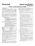
5 3. Mount the case back to a wall or to an electrical box using the 25mm-long self-tapping screws supplied (mollies for drywall are not supplied). 4. Connect the power and data wires from the control panel to the terminals on the 6160RF as indicated in Figure 2 and Table 1. G6160RF-002-V1Y+WIRING TERMINALS(TO CONTROL PANEL)++++ Figure 2 - 6160RF Wiring Details Downloaded from manuals search engine - 2 - Table 1 - Wiring Table Keypad Control Panel Wire Color G (Data Out) Data In Green - -Aux Pwr (GND) Black + +Aux Pwr Red Y (Data In) Data Out Yellow 5. Reattach the keypad to the mounted case back. Attach the top of the keypad first, and then press the bottom section down until it snaps into place securely.
6 6. Peel off protective film on the LED panel and install the keypad labels as required. APPLICATION GUIDELINES FOR THE 6160RF Use the following guidelines when planning an installation: This is the only transceiver on the system, You want to use both the receiver and transmitter function on a single-partition system, Set the keypad to a device address assigned to the desired partition.* Enable the receiver. Program a system House ID in the control panel (this will enable the transmitter function).** Set the wireless devices that will communicate with this 6160RF to the same system House ID. You want to use only the transmitter function on a second partition, Set the keypad to a device address assigned to the desired partition.
7 * Disable the receiver. Program a DIFFERENT House ID in the 6160RF than is programmed in the control panel.*/ ** Set the wireless devices that will communicate with this 6160RF to the same House ID as the 6160RF . There is another receiver or transceiver on the system, You want to use only the transmitter function on a single-partition system, Set the keypad to a device address assigned to the Partition 1. Disable the receiver. Program a House ID in the 6160RF that matches the system House ID programmed in the control panel.* Set the wireless devices that will communicate with this 6160RF to the same House ID.
8 Notes: * On vista -40 panels and above, wireless keypads ( , 5804BD) can only be used on a single partition. This partition is programmed in field 1*48, and must match the partition assigned to the 6160RF . Wireless keys can be used on more than one partition, using a House ID programmed in the 6160RF and the devices. In this case, the wireless keys must be assigned to the same partition as the 6160RF . ** On vista -20P panels, the 6160RF will use the House ID programmed in the panel for the partition to which it is assigned. Wireless keypads can only be used on Partition 1. PROGRAMMING THE 6160RF Refer to the following procedure to program the 6160RF : STEP DESCRIPTION DISPLAY CHOICES 1.
9 Enter the program mode by pressing the [1] and [3] keys simultaneously for a few seconds within 60 seconds after applying power. 2. (Keypad Address) Enter the two-digit keypad address. Press the [ ] key to continue. Notes: (1) Refer to the control panel s installation instructions for the acceptable keypad addresses. (2) On the vista -40 and above the 6160RF s partition assignment must match the RF keypad partition assignment programmed in field (1*48). CON ADDRESS CON ADDRESS CON ADDRESS CON ADDRESS = XX XX XX XX 00-31 3. (Receiver Enable) Enter [1] to enable, or [0] to disable Receiver. Enable the receiver if RF transmitters or wireless keypads are programmed into the control and no other receivers are enabled.
10 Press the [ ] key to continue. RECEIVERRECEIVERRECEIVERRECEIVER ON [0ON [0ON [0ON [0= OFF] OFF] OFF] OFF] 1= ON 0 = OFF Downloaded from manuals search engine - 3 - STEP DESCRIPTION DISPLAY CHOICES 4. (Receiver Address) If receiver is enabled, enter the two-digit receiver address. (01-30). Note: Refer to the control panel s installation instructions for the acceptable receiver addresses. Press the [ ] key to continue. REC ADDRESSREC ADDRESSREC ADDRESSREC ADDRESS= XXXXXXXX 00-30 5. (House ID) This prompt will only appear if the receiver is disabled. If the receiver is enabled the 6160RF will use the House ID programmed in the panel.