Transcription of KB-TZ2 TECHNICAL GUIDE - Hilti
1 K B -T Z 2 TECHNICAL GUIDEA llowable stress design for use in components and structural supports in nuclear facilitiesKB-TZ2 TECHNICAL Guide2 April 2021 Allowable stress design informationThe load tables in this section were developed for use in NQA projects utilizing allowable stress anchorage design when appropriate per their design basis. The load values were developed based on testing per ACI and ASTM E488. Additional information, including complete details on this product, data development, product specifications, general suitability, installation, corrosion, ordering information, and spacing and edge distance guidelines, will be included in the North American Product TECHNICAL GUIDE : Volume 2: Anchor Fastening TECHNICAL GUIDE , Edition 21 (PTG 21).
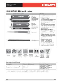
2 Figure 1 Hilti carbon steel KWIK bolt TZ2 ( KB-TZ2 )Figure 2 Hilti KB-TZ2 installedFigure 3 bolt head with length identification code and KB-TZ2 head notch embossmentTable 1A - Setting informationSetting informationSymbolUnitsNominal anchor diameter (in)1/43/81/25/83/4 Nominal bit min. 21-1/ 222-1/ 21-1/ 2122-1/ 23 -1/42-3/43 -1/443 -1/43-3/44-3/4(mm)(38)(38)(51)(64)(38)(5 1)(64)(83)(70)(83)(102)(83)(95)(121) 82-1/ 23212-1/ 233-3/43 -1/43-3/44-1/ 244-1/ 25 -1/ 2(mm)(44)(48)(64)(76)(51)(64)(76)(95)(83 ))95))114)(102)(114)(140)Min. hole -1/42-1/412-3/43 -1/44-1/43-3/44-1/44-3/44-1/44-3/45-3/4( mm)(51)(51)(70)(83)(57)(70)(83)(108)(95) (108)(121)(108)(121)(146)Installationtor que carbon steel1 Tinstft-lb4305040110(Nm)(5)(41)(68)(54)( 149)Installationtorque stainless steel1 Tinstft-lb6304060125(Nm)(8)(41)(54)(81)( 169)Fixture hole 169/1611/ 1613/16(mm)( 7.
3 9 )( )( )(17. 5 )( )1 Design information for hef = 1-1/2 is only applicable to carbon steel (CS) KB-TZ2 SteelSingle NotchStainless Steel 304 Double NotchStainless Steel 316 Triple NotchLengthIdentificationCodeLengthIdent ificationCodeLengthIdentificationCodeKB- TZ2 TECHNICAL Guide3 April 2021 Table 1B - Minimum edge distance, spacing and concrete thickness for KB-TZ2 Setting informationSymbolUnitsNominal anchor diameter (in)1/43/81/25/83/4 Effective min. 21-1/ 222-1/ 21-1/ 222-1/ 23 -1/42-3/43 -1/443 -1/43-3/44-3/4(mm)(38)(38)(51)(64)(38)(5 1)(64)(83)(70)(83)(102)(83)(95)(121)Min. member -1/43 -1/4453 -1/ 2455 -1/ 255 -1/ 265 -1/ 268(mm)(83)(83)(102)(127)(89)(102)(127)( 140)(127)(140)(152)(140)(152)(203)Carbon steelMin. edge 25 2-1/ 22-1/ 28 2-3/42-3/42-1/44-1/ 23 -1/ 22-3/45 4 3 -1/ 2(mm)(38)(127)(64)(64)(203)(70)(70)(57)( 114)(89)(70)(127)(102)(89)for s 28 6 5 12 5 -1/ 29-3/45 -1/46 -1/ 25 -1/ 27-1/410 5-3/45 -1/ 2(mm)(38)(203)(152)(127)(305)(140)(248)( 133)(165)(140)(184)(254)(146)(140)Min.
4 Anchor 25 2-1/42 12 3 -1/ 23 2 4-1/ 22-3/42-1/44-1/ 23-3/43-3/4(mm)(38)(127)(57)(51)(305)(89 )(76)(51)(114)(70)(57)(114)(95)(95)for c 28 3 -1/ 24 8 10 8 4-3/45 -1/ 27 4-1/467-1/ 24-3/4(mm)(38)(203)(89)(102)(203)(254)(2 03)(121)(140)(178)(108)(152)(191)(121)St ainless steelMin. edge 25 2-1/ 22-1/ 2 2-3/42-1/ 22-1/44 3 -1/42-1/45 4 3-3/4(mm)(38)(127)(64)(64) (70)(64)(57)(102)(83)(57)(127)(102)(95)f or s 28 5 5 5 -1/ 24-1/ 25 -1/47 5 -1/ 27 11 7-1/ 25-3/4(mm)(38)(203)(127)(127)(140)(114)( 133)(178)(140)(178)(279)(191)(146)Min. anchor 25 2-1/42-1/4 2-3/42-1/ 22 5 -1/ 22-3/43 5 4 4 (mm)(38)(127)(57)(57) (70)(64)(51)(140)(70)(76)(127)(102)(102) for c 28 4 3 -1/ 2 4-1/ 85 4-3/45 -1/ 24 4-1/48 6 5 -1/4(mm)(38)(203)(102)(89) (105)(127)(121)(140)(102)(108)(203)(152) (133)For SI: 1 inch = mmsch hmincmin at s smin at c csedge distance (c)spacing (s)Figure 4 Interpolation of minimum edge distance and anchor spacingKB-TZ2 TECHNICAL Guide4 April 2021 Table 3 - Ultimate Hilti carbon steel KB-TZ2 strength in uncracked concrete for hammer drill and core drill installations1 Nominal anchor embedmentin.
5 (mm)Nominal embedment in. (mm)TensionShearf c = 3000 psi( MPa)lb (kN)f c = 4000 psi( MPa)lb (kN)f c = 5000 psi( MPa)lb (kN)f c = 6000 psi( MPa)lb (kN)f c = 3000 psi( MPa)lb (kN)f c 4000 psi( MPa)lb (kN) 1/4 1-1/ 21-3/42,4212,5652,6832,7831,5851,652(38) (44)( )( )(11. 9 )( )( )( 7. 3 )3/81-1/ 21-7/ 83,6003,8374,0324,19 83,74 4(38)(48)( )( )(17. 9 )( )( )22-1/ 24,8305,1735,4555,6983,74 4(51)(64)( )( )( )( )( )2-1/ 235,5576,15 36,6587,10 23,74 4(64)(76)( )( 27. 4 )( )( )( )1/21-1/ 223,6004,3705,0795,74 36,7077, 5 7 7(38)(51)( )( )( )( )( )( )22-1/ 25,6116,3286,9487, 4 9 86,7077, 5 7 7(51)(64)( )( )( )( )( )( )2-1/ 237,1177,7 3 58,2518,6986,7077, 5 7 7(64)(76)( )( )( )( )( )( )3 -1/43-3/49,17710,14 810,97211,6 9 56,7077, 5 7 7(83)(95)( )(4 )( )( )( )( )5/82-3/43 -1/47, 24 68,5059,63110,66111,6 5 0(70)(83)( )( 37.)
6 8 )( )(47. 4 )( )3 -1/43-3/410,31911,85413,19 914,41111,6 5 0(83)(95)( )( )( )(6 )( )44-1/ 210,79512,62514,25715,74 511,6 5 0(102)(114)( )( )( )( )( )3/43 -1/4412,01413,27914,35215,29215,120(83)( 102)( )( )( )( )( 6 7. 3 )3-3/44-1/ 215,63917, 0 8 818,30419,36215,120(95)(114)( )( )( )(8 )( 6 7. 3 )4-3/45 -1/ 217, 9 1420,06721,91423,54815,120(121)(140)( )( )( 97. 5 )( )( 6 7. 3 )1 Testing performed in accordance with ACI and ASTM TECHNICAL Guide5 April 2021 Table 4 - Allowable Hilti carbon steel KB-TZ2 strength in uncracked concrete for hammer drill and core drill installations1,2,3,4 Nominal anchor embedmentin. (mm)Nominal embedment in. (mm)TensionShearf c = 3000 psi( MPa)lb (kN)f c = 4000 psi( MPa)lb (kN)f c = 5000 psi( MPa)lb (kN)f c = 6000 psi( MPa)lb (kN)f c = 3000 psi( MPa)lb (kN)f c 4000 psi( MPa)lb (kN) 1/4 1-1/ 21-3/4605641671696396413(38)(44)( )( )( )( )( )( )3/81-1/ 21-7/ 89009591,0081,050936(38)(48)( )( )( )( )( )22-1/ 21,2081,2931,3641,424936(51)(64)( )( )( )( )( )2-1/ 231,3891,5381,6651,776936(64)(76)( )( )( 7.
7 4 )( 7. 9 )( )1/21-1/ 229001,0921,2701,4361,6771,894(38)(51)( )( )( )( )( 7. 5 )( )22-1/ 21,4031,5821,7371,8751,6771,894(51)(64)( )( 7. 0 )( )( )( 7. 5 )( )2-1/ 231,7791,9342,0632,1751,6771,894(64)(76) ( 7. 9 )( )( )( )( 7. 5 )( )3 -1/43-3/42,2942,5372,74 32,9241,6771,894(83)(95)( )(11. 3)( )( )( 7. 5 )( )5/82-3/43 -1/41, 8112,1262,4082,6652,913(70)(83)(8 .1)( )( )(11. 9 )( )3 -1/43-3/42,5802,9633,3003,6032,913(83)(9 5)(11. 5 )( )( )( )( )44-1/ 22,6993,15 63,5643,9362,913(102)(114)( )( )( )(17. 5 )( )3/43 -1/443,0033,3203,5883,8233,780(83)(102)( )( )( )(17. 0 )( )3-3/44-1/ 23,9104,2724,5764,8413,780(95)(114)(17. 4 )( )( )( )( )4-3/45 -1/ 24,4795,0175,4785,8873,780(121)(140)( )( )( )( )( )1 Intermediate load values for other concrete strength and embedments can be calculated by linear interpolation2 Allowable load calculated using a factor of safety of Apply spacing, edge distance, and concrete thickness factors in tables 7 to 11 as necessary.
8 4 With the exception of 3/4 diameter KB-TZ2 strength, all of the load values in this table can be utilized for either hammer or core drilled installations. Refer to Tables 5 and 6 for 3/4 diameter core strength TECHNICAL Guide6 April 2021 Table 5 - Ultimate Hilti carbon steel KB-TZ2 strength in uncracked concrete for core drill installations1 Nominal anchor embedmentin. (mm)Nominal embedment in. (mm)TensionShearf c = 3000 psi( MPa)lb (kN)f c = 4000 psi( MPa)lb (kN)f c = 5000 psi( MPa)lb (kN)f c = 6000 psi( MPa)lb (kN)f c = 3000 psi( MPa)lb (kN)f c 4000 psi( MPa)lb (kN)3/43 -1/449,82610,84112,66114,28015,120(83)(1 02)( )( )( )( )( 6 7. 3 )3-3/44-1/ 211, 5 4 412,85015,22017, 3 5 415,120(95)(114)( )( 57. 2 )( 6 )( 7 7.)
9 2 )( 6 7. 3 )4-3/45 -1/ 216,49218,21021,29023,54815,120(121)(140 )( )( )( )( )( 6 7. 3 )1 Testing performed in accordance with ACI and ASTM 6 - Allowable Hilti carbon steel KB-TZ2 strength in uncracked concrete for core drill installations1,2,3 Nominal anchor embedmentin. (mm)Nominal embedment in. (mm)TensionShearf c = 3000 psi( MPa)lb (kN)f c = 4000 psi( MPa)lb (kN)f c = 5000 psi( MPa)lb (kN)f c = 6000 psi( MPa)lb (kN)f c = 3000 psi( MPa)lb (kN)f c 4000 psi( MPa)lb (kN)3/43 -1/442,4562,7103,16 53,5703,780(83)(102)( )( )( )( )( )3-3/44-1/ 22,8863,2133,8054,3393,780(95)(114)( )( )( )( )( )4-3/45 -1/ 24,1234,5525,3235,8873,780(121)(140)( )( )( )( )( )1 Intermediate load values for other concrete strength and embedments can be calculated by linear interpolation2 Allowable load calculated using a factor of safety of Apply spacing, edge distance, and concrete thickness factors in tables 7 to 11 as TECHNICAL Guide7 April 2021 Table 7 - Load adjustment factors for carbon steel 1/4-in.
10 Diameter KB-TZ2 in uncracked concrete11/4 -in. KB -TZ 2uncracked concreteSpacing factor in tensionfANEdge distance factor in tensionfRNSpacing factor in shear2fAVEdge distance in shearConcrete thickness factor in shear3fHV Towar dedgefRV To edgefRVEffective embedment hefin.(mm)1-1/2 (38)1-1/2 (38)1-1/2 (38)1-1/2 (38)1-1/2 (38)1-1/2 (38)Nominal embedment hnomin.(mm)1-3/4 (44)1-3/4 (44)1-3/4 (44)1-3/4 (44)1-3/4 (44)1-3/4 (44)Spacing (s) / Edge Distance (ca) / Concrete Thickness (h) in. (mm)1-1/ 2(38) (51) 2(64) (76) -1/4(83) -1/ 2(89) (102) (127) (152) (178) (203) (229) > 12(305) Linear interpolation not permitted2 Spacing factor reduction in shear, fAV, is applicable when edge distance c < 3hef . If c 3hef then fAV = Concrete thickness reduction factor in shear, fHV, is applicable when edge distance c < 3hef.