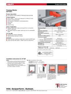
Transcription of HILTI TECHNICAL BULLETIN
1 HILTI TECHNICAL BULLETIN Date: March 4, 2018 Subject: HIT-HY 270 TECHNICAL Data for Masonry Construction HILTI has tested and evaluated HIT-HY 270 adhesive anchor system in masonry in accordance with ASTM E1512, ASTM E488, ICC-ES AC58 and AC60. Data for hollow (ungrouted) and fully grouted concrete masonry walls, and hollow (ungrouted) brick masonry walls are published in ESR-4143. ESR-4144 contains data for unreinforced brick masonry for seismic retrofit applications. Tables in this TECHNICAL BULLETIN are developed based on the Allowable Stress Design approach using published data in ESR-4143, ESR-4144, and internal testing information.
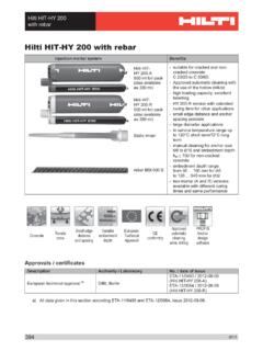
2 Section of the HILTI North American Product TECHNICAL Guide, Volume 2: Anchor Fastening TECHNICAL Guide, Edition 17 (2017 PTG) provides detailed explanations of the Allowable Stress Design provisions used by HILTI . Please feel free to contact our Engineering TECHNICAL Services department for more information or any questions. HILTI Engineering TECHNICAL Services United States HILTI Engineering TECHNICAL Services Canada (877) 749-6337 toll free (800) 363-4458 toll free Figure 1 HILTI HIT-HY 270 specifications for HAS threaded rod and reinforcing bars in grout-filled concrete masonry walls HILTI installation specifications for HAS threaded rod in grout-filled concrete masonry walls Setting information Symbol Units Nominal rod diameter (in.)
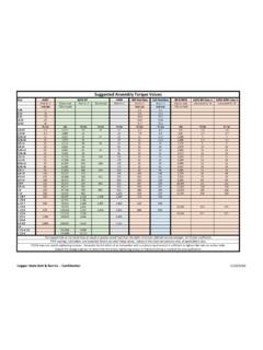
3 3/8 1/2 5/8 3/4 Nominal bit diameter d0 in. 7/16 9/16 3/4 7/8 Nominal / effective embedment h0 / hef in. 3-3/8 4-1/2 5-5/8 6-3/4 (mm) (86) (114) (143) (171) Installation torque Tinst ft-lb 6 10 (Nm) (8) (10) (10) ( ) Diameter of fixture hole df in. 7/16 9/16 11/16 13/16 HILTI installation specifications for reinforcing bars in grout-filled concrete masonry walls Setting information Symbol Units Rebar size #3 #4 #5 #6 Nominal bit diameter d0 in. 1/2 5/8 3/4 7/8 Nominal / effective embedment h0 / hef in. 3-3/8 4-1/2 5-5/8 6-3/4 (mm) (86) (114) (143) (171) HIT-HY 270 TECHNICAL Data for Masonry Construction Page 2 April 2018 Table 1 HILTI HIT-HY 270 allowable adhesive bond tension loads for threaded rods and reinforcing bars in the face of grout-filled concrete masonry walls1,2,3,4,5,6,7,8 Nominal anchor diameter in.
4 Rebar size Effective embedment in. (mm)11 Tension lb (kN) Spacing9 Edge distance10 Critical scr in. (mm) Minimum smin in. (mm) Load reduction factor @ smin12 Critical ccr in. (mm) Minimum cmin in. (mm) Load Reduction Factor @ cmin12 3/8 3 3-3/8 1,240 12 (86) ( ) (343) (305) 1/2 4 4-1/2 2,035 18 20 (114) ( ) (457) 4 (508) 4 5/8 5 5-5/8 2,840 (102) 20 (102) (143) ( ) (572) (508) 3/4 6 6-3/4 3,810 27 20 (171) ( ) (686) (508) Table 2 - HILTI HIT-HY 270 allowable adhesive bond shear loads for threaded rods and reinforcing bars in the face of grout-filled concrete masonry walls 1,2,3,4,5,6,7,8 Nominal anchor diameter in.
5 Rebar size Effective embedment in. (mm)11 Shear lb (kN) Spacing9 Edge distance10 Critical scr in. (mm) Minimum smin in. (mm) Load reduction factor @ smin12 Critical ccr in. (mm) Minimum cmin in. (mm) Load reduction factor @ cmin12 Load perpendicular to edge Load parallel to edge 3/8 3 3-3/8 850 12 (86) ( ) (343) (305) 1/2 4 4-1/2 1,495 18 12 (114) ( ) (457) 4 (305) 4 5/8 5 5-5/8 2,615 (102) 20 (102) (143) ( ) (572) (508) 3/4 6 6-3/4 4,090 27 20 (171) ( ) (686) (508) The following footnotes apply to both Tables 1 and 2.
6 1 All values are for anchors installed in fully grouted concrete masonry with minimum masonry prism strength of 1,500 psi. Concrete masonry units shall be lightweight, medium-weight or heavy-weight conforming to ASTM C90. Allowable loads are calculated using a safety factor of 5. 2 Anchors may be installed in any location in the face of the masonry wall including cell, web, and mortar joints. Anchors are limited to one per masonry cell. See Figure 2. 3 Linear interpolation of load values between minimum spacing (smin) and critical spacing (scr) and between minimum edge distance (cmin) and critical edge distance (ccr) is permitted.
7 4 Concrete masonry thickness must be equal to or greater than times the anchor embedment depth. EXCEPTION: the 5/8-inch- and the 3/4-inch diameter anchors (No. 5 and No. 6 bars) may be installed in minimum nominally 8-inch thick concrete masonry. 5 When using the basic load combinations in accordance with IBC Section , tabulated allowable loads must not be increased for seismic or wind loading. When using the alternative basic load combinations in IBC Section that include seismic or wind loads, tabulated allowable loads may be increased by 33-1/3 percent, or the alternative basic load combinations may be reduced by a factor of 6 Allowable loads must be the lesser of the adjusted masonry or bond tabulated values and the steel values given in tables 3 and 4.
8 7 Tabulated allowable loads shall be adjusted for increased base material temperatures in accordance with figure 12. 8 For combined loading: (Tapplied / Tallowable)n + (Vapplied / Vallowable)n 1, where n=5/3 for 3/8- and 1/2-inch diameters (No. 3 and No. 4 rebar) and n=1 for 5/8 and 3/4-inch diameter or No. 5 and No. 6 rebar. 9 The critical spacing, scr, is the smallest anchor spacing where full load values may be used. The minimum spacing, smin, is the minimum anchor spacing for which values are available and installation is recommended.
9 Spacing is measured from the center of one anchor to the center of an adjacent anchor. 10 The critical edge distance, ccr, is the smallest edge distance where full load values may be used. The minimum edge distance, cmin, is the minimum edge distance for which values are available and installation is recommended. Edge distance is measured from the center of the anchor to each edge. 11 Embedment depth is measured from the outside face of the concrete masonry unit. 12 Load reduction factors are multiplicative: both spacing and edge distance load reduction factors, and spacing and edge distances for all adjacent anchors/edges less than smin/cmin, must be considered.
10 Load values for anchors installed at less than scr and ccr must be multiplied by the appropriate load reduction factor based on actual edge distance (c) and spacing (s). HIT-HY 270 TECHNICAL Data for Masonry Construction Page 3 April 2018 Table 3 - HILTI HIT-HY 270 allowable tension and shear values for threaded rods based on steel strength 1,2,3 Anchor diameter in. Tension, lb (kN) Shear, lb (kN) ISO 898 Class ASTM A36 ASTM F1554 Gr. 55 ASTM A307 ASTM A193 B7 ASTM F593 CW (316/304) ISO 898 Class ASTM A36 ASTM F1554 Gr.