Transcription of A review of the concepts behind anchoring columns, as ...
1 MODERN STEEL CONSTRUCTION june 2010 Base Plates and Anchor RodssteelwiseA review of the concepts behind anchoring columns, as further explained in AISC Steel Design Guide RODS AND BASE PLATES typically are among the last components of a structural steel building to be designed, and yet they are the first components to be placed. Design equations, guidance on availability of materials and constructability, and similar basics are covered in AISC Steel Design Guide 1: Base Plate and Anchor Rod Design. This article high-lights a number of engineering, fabrication, and erec-tion considerations that will aid in the overall design, detailing, and erection processes for column bases and repair, too, when that is A in the 2005 AISC Specification for Struc-tural Steel Buildings (ANSI/AISC 360-05) lists the materials that can be used for structural steel base plates and anchor rods.
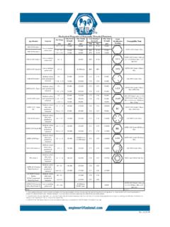
2 Based upon this, Table 1 lists common base plate materials, and the range of avail-able thicknesses for these materials. Table 2 lists com-mon anchor rod materials and the range of diameters for these materials. As illustrated in Tables 1 and 2, the yield points and tensile strengths can change with the thickness or diameter of the A36 is the usual material for base plates, and has the widest availability. However, when column bases are designed to resist uplift or large moments, ASTM A572 grade 50 material may be more appropri-ate for economy. ASTM f1554 is the usual material for anchor rods, and grade 36 has the widest availability. Grades 55 and 105 are used when there is uplift or large moments. It is good practice to verify the availability of base plate and anchor rod materials with the structural steel fabricator prior to the design of the column bases with material other than the usual BasicsColumn bases generally can be classified in two categories: exposed bases (as illustrated in Figure 1) or embedded bases (as illustrated in Figure 2).
3 Both types generally consist of the same components: a steel column, base plate, anchor rods, grout, and con-crete foundation. Each component is designed to per-form its function in the transfer of the forces from the building into the jacinda collins, and Thomas j. schlaflyTable 1 Base Plate Materialsmaterial asTmThickness (in.)yield Point (ksi)a36over 832 to 836a572 to 642 to 450a588> 5 to 842> 4 to 546 to 450 Table 2 Anchor Rod Materialsmaterial asTmThickness (in.)Tensile strength, Fu (ksi)a36 to 458a193 Gr B7 2 100> 2 to 4115> 4 to 7125a307 (obsolete) to 458a354 Gr Bd2 to 4140 to 2 150a4491 to 3901 to 1 105 to 1120f1554Gr 36 to 458Gr 55 to 475Gr 105 to 3125 Jacinda Collins, , is an advisor in AISC s Steel Solutions Center. Thomas J. Schlafly is director of research at the American Institute of Steel Construction, Chicago. june 2010 MODERN STEEL CONSTRUCTION Most column bases are designed for compressive axial loads.
4 Braced-frame column bases also are designed for horizontal shear, and may in some cases be subject to tensile axial loads. Moment-frame column bases are designed for a combination of axial compression, moment, and horizontal shear bases subjected to axial compression, the compressive force is distributed from the steel column to the base plate in direct bearing. For column bases subjected to axial tension, the tensile force is distributed from the steel column to the anchor rods. Depending on the ratio of axial compression to moment, column bases subjected to moments will distribute the force couple from the column to the foundation through a combination of bearing of the base plate and tension in some of the anchor rods. For column bases subjected to shear, the shear forces are resisted at the interface between the base plate and the foundation, and this mechanism must be selected by the hooked rods may be less expensive when compared to headed rods or threaded rods with a nut, it is rec-ommended that hooked rods not be used when-ever there is a calculated tension force on the rods.
5 Why? Hooked rods have limited pullout strength, due to the bearing mechanism and tendency to slip under tension loads espe-cially when the oil from cutting threads remains on the column bases subject to moment or uplift, the loads can be transferred through bending of the base plate. How-ever, when the uplift or moment results in large tension forces, a boot detail with stiffeners attached to the column can be utilized. These stiffeners transfer the forces from the column flange to the anchor rods directly, thereby avoiding bending in the base use of anchor rods to transfer shear forces is not rec-ommended and should only be used with caution. The holes in base plates for anchor rods are large, and this tends to make it difficult to ensure that the shear force can be trans-ferred. If a column base is designed to transfer shear forces to the anchor rods, care must be taken to account for the effect of the size of the holes in the base plate.
6 This often is done with a washer with a standard hole. Note that the anchor rods in this case must be designed for bending between the washer and the concrete the shear forces being transferred from the column are relatively small, it is possible to transfer the shear forces by fric-tion due to the dependable axial compression load, or by shear friction, between the base plate and the grout or the surface of the foundation. Larger shear forces may require that the force be transferred through the embedment of the column base (Figure 2) or with the use of a shear lug (Figure 3). In addition, tie rods and hairpin reinforcing bars (Figure 4) can be used to transfer the large shear forces from the column base to the con-crete FixityThe design and detailing of column bases for fixity either to prevent it or to achieve it is very important. Column bases subject to high-seismic loads also require consideration to provide the desired ductile behavior of the seismic load resist-ing system.
7 Requirements for high-seismic column bases are provided in the AISC Seismic Provisions (AISC 341-05).Most pinned connections have a small amount of restraint, and most rigid connections can experience rotation. Com-mon details are configured to limit restraint and rotation to amounts that can be assessing the rotation of the base, it must be rec-ognized that each of the components of a column base (soil, foundation, anchor rods, base plate, steel column, etc.) con-tributes to the stiffness and flexibility of the column base. Each component s contribution must be included in the evaluation of the fixity of the base as well as their effect on the behavior of the other components of the rotation of an isolated column foun-dation must be reduced, the use of grade beams is an option (Figure 5). grade beams can be reinforced concrete or composite with struc-tural steel encased in the plates usually are attached to the column during the fabrication of the structural steel and delivered as one the columns and/or base plates are very heavy, it can be difficult to deliver and set them as one piece.
8 In these Figure 1 Figure 2 Figure 3 Figure 4 Figure 5 MODERN STEEL CONSTRUCTION june 2010instances, the base plate is set using leveling screws attached to the sides of the plate (see Erection later in this article) and then grouted. The column is then set on top of the base plate with the aid of connection angles or pedestals that are welded directly to the col-umn and do not bear on the base plate. The column is set by attaching the anchor rods to the connection angles or pedestals, and there is no need to then weld to the base plate to column when using this base plates are welded to the col-umns, it is recommended that fillet welds be used whenever possible for the base plate to column connection. Note that minimum fillet weld size requirements have been updated in the 2005 AISC Specification; the size of the fillet weld is now based on the thinner of the materials being connected.
9 In addition, the weld-all-around symbol should be avoided. One labor saving weld-ing technique is to provide an arrangement of fillet welds that permits the base plate to be attached to the column without having to rotate the column. This can be accom-plished by welding the outside face of one flange and the inside face of the opposite flange of the proper setting method for the base plate must be established before construc-tion. Care should be taken to identify if the top or bottom of the base plate is to be set to a specified elevation. The proper elevation can be particularly significant when during the fabrication process the top of the base plate is milled and the bot-tom of the base plate is left as rolled, thus leaving a plate that may be a little thicker than design parameters. It is considered good practice for the fabricator to identify any significant dimensional changes of the base plate on the erection drawings prior to columns and base plates are placed, leveling of the column base or loose plate commonly is achieved by one of the following methods:1.
10 Leveling nuts and washers on anchor rods beneath the base plate2. Leveling screws (common for heavy loose base plates)3. Shim stacks between the base plate and the supporting foundation (Figure 6)4. Leveling plates (which also serve as anchor rod templates)After placement of the base plate, the anchor rods are snug tightened to hold the column plumb. It should be understood that anchor rods cannot be pretensioned like bolts in a steel-to-steel high-strength bolted joint. Anchor rods will relax and lose any pretension as the bond along the length of the rod releases and creep occurs in days or weeks after concrete contractor places the anchor rods and the general contractor places the non-shrink grout between the base plate and the foundation. In between, the steel erector erects the column and base plate. Hence, the general contractor also must coordinate this process so that the rods are located properly and the grout is placed in a timely manner so that steel erection can AISC Code of Standard Practice (AISC COSP) gives the tolerances for anchor rod placement that are required to properly position the column base on the anchor rods.