Transcription of KV - FOAM CHAMBER
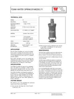
1 foam CHAMBER MODEL - FC. TECHNICAL DATA : MODEL FC. SIZE 50, 65, 80, 100 &150 NB. inlet WORKING PRESSURE Minimum Kg. / sq. cm. (40 PSI). Maximum 7 Kg. / (100. PSI). FLANGE CONNECTION ANSI Class 150#. APPROXIMATE FC 50- Kg. WEIGHT FC 65- Kg. FC 80- Kg. FC 100- Kg. FC Kg. SPECIFICATION. foam CHAMBER is an air aspirating foam discharge device, VAPOUR SEAL to (10 PSI. covering wide range of flow from 75 to 3600 litres per minute TO 25 PSI). at to 7 inlet pressure. The foam CHAMBER contains a vapour seal to prevent the entry of vapour into the RUPTURE PRESSURE Running water/Water foam foam CHAMBER and the foam solution pipe. Each foam solution pressure at the CHAMBER is supplied with an orifice plate, designed for the inlet of foam CHAMBER . required flow and inlet pressure. The orifice is field replaceable in the event of change in design parameters. MAXIMUM ( PSI). The foam is produced by introducing air into the foam PERMISSIBLE BACK.
2 Solution stream. The inlet of foam CHAMBER is designed to PRESSURE ON create venturi jet which draws air into the foam solution VAPOUR SEAL stream. The air is drawn into the foam solution through the holes located on the foam CHAMBER covered with stainless FINISH Red epoxy painted steel screen to exclude nesting birds and insects. The aerated foam is directed into the deflector for the gentle ORDERING a) Model and size application of the expanded foam . The deflectors are INFORMATION b) Inlet pressure. available in different models. c) foam solution flow reqd. d) Inlet, outlet flange On removal of cover plate from the top of the CHAMBER allows specification. the system to be tested and to draw a sample of the e) Type of foam concentrate expanded foam , without removing the vapour seal or used. disconnecting the foam CHAMBER from the tank. Frangible APPLICATION glass bursting disc (vapour seal) can be replaced very easily.
3 foam CHAMBER is used in one of the most common application to protect vertical fixed roof (cone) liquid storage SYSTEM DESIGN REQUIREMENT. tanks, with or without internal floating roof with the low The NFPA-11, a standard for low expansion foam , provides expansion foam system. The application of foam is on the the essential requirement of an appropriate designed foam basis that the risk comprises the total surface area of the pouring system, which are identified and outlined as below: fuel. The foam system design guidelines generally used The foam Deflector is used with the foam CHAMBER . are in accordance with NFPA-11, standard. The aerated foam from the foam CHAMBER is directed in to foam Chambers are defined by NFPA-11 as Type II discharge the deflector for the gentle application of the expanded foam . outlets for delivering the foam to the surface of a flammable The deflector reduces the expanded foam velocity and al- liquid.
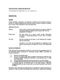
4 The foam Chambers are widely used with the In-line lows the foam to slide down the tank wall. foam inductor, Balance pressure foam proportioning system, Bladder tank proportioner or foam tender. PAGE 1 OF 6. a) Number of foam CHAMBER The number of foam chambers required is determined by the tank diameter. Where two or more foam chambers are required, they shall be spaced equally around the tank periphery and each foam CHAMBER shall be sized to deliver Selection Of KV foam CHAMBER foam at an approximately same rate. Please refer graph to SIZE OF foam K-FACTOR. select the unit that will provide the required minimum foam CHAMBER . solution application rate at the available operating pressure 50 NB to 127. of the foam CHAMBER . For minimum number of foam CHAMBER requirement, kindly follow the recommendations 65 NB to 254. as per NFPA/OISD/TAC or as per the governmental codes 80 NB to 508. or ordinances wherever applicable. 100 NB to 1016.
5 B) Minimum foam Solution Application Rate 150 NB The minimum foam solution application rate is the rate at which the water and foam concentrate in correctly proportioned ratio should be delivered to the surface of a To select the size of the foam CHAMBER use the following storage tank under protection to control and extinguish the formula fire. For minimum application rate requirement follow the Q=K P. recommendations as per NFPA/OISD/TAC or governmental Q = Total solution flow in litres per minute. codes or ordinances wherever applicable. K = Constant for foam CHAMBER P = Inlet pressure in Testing And Maintenance Qualified and trained person must commission the system. Example After few initial successful tesst an authorized person must To find K-Factor be trained to perform inspection and testing of the system. Q = 300 LPM. It is recommended to carry out physical inspection of the P = system regularly. The system must be fully tested at least K = 300 = once in a year or in accordance with applicable NFPA/OISD/.
6 TAC standards or in accordance with standards of the This K-Factor falls within the range of the foam CHAMBER organization having local jurisdiction. having 65 NB size. Hense 65 NB size of foam CHAMBER should be selected. Do not turn off the system or any valve to make repair or test The foam CHAMBER size may also be selected with the the system, without placing a roving Fire Patrol in the area help of the graph. covered by the system. The Patrol should continue until the system is put back in service. Also inform the local security Calculation example guard and control alarm station, so as to avoid false alarm. Tank type : Fixed roof storage tank Tank diameter : 40 meters. Each system is to be flushed properly. The vapour seal must foam concentrate to be used : AFFF 3%. be replaced if the system has been operated. Normal testing Pressure at inlet of foam CHAMBER : of the CHAMBER can be carried out by removing the cover Flash point of liquid stored in tank : - 27 C.
7 Plate from the top of the CHAMBER . This allows the system Surface area = d2 4 = ( X 402.) 4. to draw a sample of the expanded foam without removing the vapour seal or disconnecting the foam CHAMBER from = 1256 Sq. mts. the tank. a) foam solution application rate = * LPM /Sq. mts. X Surface area The air screen is to be inspected periodically for the = X 1256. obstruction of air inlet holes. If any obstruction is noticed, = 5150 LPM. remove the same and flush if necessary. * LPM is as per NFPA-11 ( 5 LPM as per OISD. recommendations ) or it should be as per prevailing It is recommended to have regular maintenance programme rules of local authority having jurisdiction. to inspect the Vapour Seal CHAMBER discharge area and deflector for possible deposit or obstruction. b) Number of foam CHAMBER required for 40 metres diameter tank = 3 nos. minimum (Reference NOTE NFPA-11). A PROVISION IS TO BE MADE FOR PRESSURE GAUGE. MOUNTING AT INLET OF foam CHAMBER , WHICH CAN Capacity of foam CHAMBER required BE PLUGGED AFTER SUCCESSFUL COMMISSIONING = 5150 3.
8 OF THE SYSTEM. THIS WILL HELP TO ANALYSE THE SYS- = 1717 LPM. TEM WHILE COMMISSIONING. The K-Factor for flow of 1718 LPM at K = Q P = 1717 = PAGE 2 OF 6. The K-Factor ( ) falls within the K-Factor of 100 NB. size of the foam CHAMBER . Hence three numbers of 100. NB foam CHAMBER with 1717 LPM capacity at inlet pressure are to be selected. Note THE ABOVE ARE THEORETICAL CALCULATIONS. IT IS, THEREFORE, RECOMENDED THAT SYSTEM DESIGNER. CONSIDERS AN APPROPRIATE FACTOR OF SAFETY. c) foam Concentrate Requirement : The fuel stored has flash point of 27 C. So the minimum system running duration recommended is 55 minutes. (Reference NFPA-11). The foam foam solution percentage system concentrate = application X of foam X running required rate in LPM concentrate time 3. = 5154 X X 55. 100. = 8505 litres. Add 5% = 8930 litres. The supplementary hose stream requirement is also to be considered and 100% reserve stock to be maintained or as per local authority having jurisdiction.
9 The additional quantity of 5% is general guideline, however system designer has to work-out this percentage considering factor of safety, pipeline, minimum level for induction in storage tanks etc. Note 1. It is recommended to select next higher size of foam CHAMBER when the K-Factor is very much close to upper limit of the model. 2. For the best performance the inlet pressure at the foam CHAMBER should be or higher. PAGE 3 OF 6. foam CHAMBER . DIMENSION in millimetre ( Approximate ) PART LIST. INLET OUTLET ITEM DESCRIPTION MATERIAL. A B C. ( F1 ) (F2) SPECIFICATION. NO. 50 NB 80 NB 630 518 160 1 ORIFICE PLATE 304. 2 INLET FLANGE STEEL ASTM A105. 65 NB 100 NB 720 589 175. 3 AERATING PIPE STEEL PIPE. 80 NB 150 NB 1050 895 225 4 foam MAKING CHAMBER STEEL PIPE. 5 foam CHAMBER STEEL PIPE. 100 NB 200 NB 1175 986 275. 6 CHAMBER FLANGE STEEL. 150 NB 250 NB 1250 1020 325 7 GASKET NEOPRENE. 8 INSPECTION HATCH STEEL. 9 BOLT STEEL.
10 - Dimension of inlet / outlet flanges ( F1 / F2 ) are as per ANSI 10 VAPOUR SEAL RING & SEAT STEEL. 11 VAPOUR SEAL GLASS. - Pipes used are ERW (Seamless Pipes are optional on 12 WING NUT & STUD 304. request). 13 DISCHARGE PIPE STEEL PIPE. 14 OUTLET FLANGE STEEL ASTM A105. 15 AIR STRAINER 304. 16 CHAMBER PLATE STEEL. PAGE 4 OF 6. PRESSURE VS FLOW PERFORMANCE CHARACTERISTIC. 400 2600. foam SOLUTION FLOW (LPM). 2400. foam SOLUTION FLOW (LPM). 2200. 300. 2000. 1800. 200 1600. 1400. 1200. 100. 1000. 800. 2 3 4 5 6 7 8 2 3 4 5 6 7 8. INLET PRESSURE ( ) INLET PRESSURE ( ). SIZE 50NB SIZE 100NB. foam SOLUTION FLOW (LPM) 4000. 3700. 800. 3400. foam SOLUTION FLOW (LPM). 3100. 600. 2800. 2500. 400. 2200. 200 1900. 1600. 2 3 4 5 6 7 8 2 3 4 5 6 7 8. INLET PRESSURE ((KG/CM. KG/SQCM)) INLET PRESSURE ( ). SIZE 65NB SIZE 150NB. 1400. 1200. foam SOLUTION FLOW (LPM). 1000. 800. 600. 400. 2 3 4 5 6 7 8. INLET PRESSURE ( ). SIZE 80NB. PAGE 5 OF 6.