Transcription of LAB 2: Measuring Capacitance
1 _____ P443 L2 1 LAB 2: Measuring Capacitance 1. Introduction Capacitance A voltage difference V applied between two conductors will induce opposite charges +Q and Q on each. Capacitance is the ratio of the induced charge to the applied voltage, C=Q/V, and is determined only by the shape of the conductors and the spacing between them. Capacitors are used to temporarily store electric charge and energy. They are also used to condition signals in analog and digital circuits. In today s lab we will construct a system for Measuring Capacitance and use this to investigate two situations.
2 First, you will measure the Capacitance of a pair of circular plates separated by thin sheets of polycarbonate and use your results to find the dielectric constant of this material. Second, you will determine the Capacitance of a pair of rectangular plates as a function of the separation between them. At small plate separations we expect the Capacitance to follow the simple formula C=A 0/d, but for separations comparable to the width of the plates, the situation becomes more complex. In class you will use numerical techniques to calculate the Capacitance in this case.
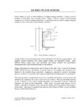
3 We reference an analytical solution below. Determining Capacitance from AC Impedance We can measure the Capacitance of an element by applying an AC voltage across it while we measure the AC current through it. A short detour into AC circuit theory explains how this works: In AC circuits the current and voltage vary sinusoidally with time at some frequency f = /2 . For example, in the circuit below a voltage source produces an AC voltage, and an AC current flows through a component with impedance Z. Vin=V0cos( t) I=I0cos( t+ ) Z vin _____ P443 L2 2 It is convenient to work with the complex quantities V =V0ej t, I =I0ej( t+ ).
4 (j= 1). The complex current and voltage are related by a form of Ohm's law, V =Z I . The impedance Z of resistors, capacitors and inductors are given by the following formulas, and we note that the impedance of capacitors and inductors depend on frequency. Resistor Z R= R resistors are frequency independent Capacitor ZC = (j C)-1 capacitors block DC Inductor ZL= j L inductors block high frequency We can combine the impedance of different components in the same way as we add resistances in series and parallel.
5 In the end, we find the actual current and voltage by taking the real part of the complex quantities. The circuit we are studying can be treated as a perfect AC voltage source connected across an ideal resistor and capacitor in series. The Capacitance is due to the parallel plates (plus stray Capacitance from other parts of the circuit). The resistance includes the resistance of the wires and the output impedance of the AC voltage source. If there were no resistive component to the circuit, then the ratio of the current to voltage would be simple: !
6 IC/!VC=1/ZC=j C, and the actual measured current would be: IC(t)= CV0sin( t) . (R=0) (1) A measurement of the amplitude of the current would determine C. If the resistance of the circuit is not negligible, then the total impedance of the circuit is the sum of the impedance of the capacitor and resistor: Z=ZR+ZC=R+1j C . The ratio of the current to the voltage is then !I/!V=1/Z=1/R+1j C =j C11+jRC . _____ P443 L2 3 If the resistance is a small perturbation to the circuit ( RC <<1) we can approximate this term by expanding the fraction and keeping only terms to first order: !
7 I/!V j C1 jRC ()=RC2 2+j C (2) The actual current would then be: I(t)= 2RC2V0()cos( t)+ CV0()sin( t). (3) Our measurement will use a lock-in amplifier that can separately measure the cosine-component and sine-component of the signal. A measurement of the sine-component of the current determines C. 2. Apparatus The apparatus consists of the physical capacitors and the electronics. The physical capacitors consist of parallel circular or rectangular plates mounted on rails so that the plate separation can be varied.
8 The electronics include a function generator as an AC source and a lock-in amplifier as an AC current meter. An oscilloscope allows the operator to monitor the signal in real time. GWINSTEK AFG-2225 Function Generator: The function generator can generate two independent periodic waveforms at frequencies up to 25 MHz. The output waveform can be sinusoidal, square wave, pulse, or linear ramp. Alternately, the user can program an arbitrary waveform shape. Today we will use sinusoidal outputs at frequency f = 10 KHz for CH1 and CH2.
9 CH1 will be the voltage source for our experiment. CH2 will be used to trigger our electronics. Oscillo -scope Lock-in Amp. Function Generator CH 2. Input A/I CH 1 CH 2. CH 1 Physical Capacitor Monitor _____ P443 L2 4 Stanford Research SR-830 Lock-in Amplifier: A Lock-in Amplifier acts as an AC filter tuned to the frequency of the signal with an arbitrarily narrow pass-band. Such a filter will reject any noise that is not within the pass-band and allow the signal to be measured.
10 A typical example might use a center frequency f =10 KHz and a bandwidth f = 1Hz. Lock-in amplifiers can often recover small signals even when the noise is hundreds of times larger than the signal. A Lock-in Amplifier requires a signal at a fixed frequency and a reference. The reference is a clean AC voltage at the frequency of the signal. The Lock-in internally generates an AC voltage at the frequency of the reference. The signal is then multiplied by the AC voltage and the product is averaged over time. Noise at other frequencies averages to zero because sine-functions of different frequencies are orthogonal.