Transcription of Lab – Configuring Basic RIPv2 (Solution) - Radford
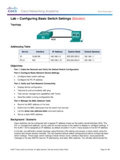
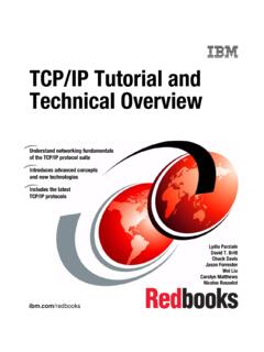
1 Lab Configuring Basic RIPv2 (Solution). Topology 2017 Cisco and/or its affiliates. All rights reserved. This document is Cisco Public. Page 1 of 15. Lab Configuring Basic RIPv2 . addressing Table Device Interface IP Address Subnet Mask Default Gateway R1 G0/1 N/A. S0/0/0 (DCE) N/A. R2 G0/0 N/A. S0/0/0 N/A. S0/0/1 (DCE) N/A. R3 G0/1 N/A. S0/0/1 N/A. S1 N/A VLAN 1 N/A N/A. S3 N/A VLAN 1 N/A N/A. PC-A NIC PC-B NIC PC-C NIC Objectives Part 1: Build the Network and Configure Basic Device Settings Part 2: Configure and Verify RIPv2 Routing Configure RIPv2 on the routers and verify that it is running. Configure a passive interface. Examine routing tables. Disable automatic summarization.
2 Configure a default route. Verify end-to-end connectivity. Background / Scenario RIP version 2 ( RIPv2 ) is used for routing of IPv4 addresses in small networks. RIPv2 is a classless, distance- vector routing protocol, as defined by RFC 1723. Because RIPv2 is a classless routing protocol, subnet masks are included in the routing updates. By default, RIPv2 automatically summarizes networks at major network boundaries. When automatic summarization has been disabled, RIPv2 no longer summarizes networks to their classful address at boundary routers. In this lab, you will configure the network topology with RIPv2 routing, disable automatic summarization, propagate a default route, and use CLI commands to display and verify RIP routing information.
3 Note: The routers used with CCNA hands-on labs are Cisco 1941 Integrated Services Routers (ISRs) with Cisco IOS Release (4)M3 (universalk9 image). The switches used are Cisco Catalyst 2960s with Cisco IOS Release (2) (lanbasek9 image). Other routers, switches, and Cisco IOS versions can be used. Depending on the model and Cisco IOS version, the commands available and output produced might vary from what is shown in this lab. Refer to the Router Interface Summary Table at the end of the lab for the correct interface identifiers. 2017 Cisco and/or its affiliates. All rights reserved. This document is Cisco Public. Page 2 of 15. Lab Configuring Basic RIPv2 . Note: Make sure that the routers and switches have been erased and have no startup configurations.
4 If you are unsure, contact your instructor. Required Resources 3 Routers (Cisco 1941 with Cisco IOS Release (4)M3 universal image or comparable). 2 Switches (Cisco 2960 with Cisco IOS Release (2) lanbasek9 image or comparable). 3 PCs (Windows 7, Vista, or XP with terminal emulation program, such as Tera Term). Console cables to configure the Cisco IOS devices via the console ports Ethernet and Serial cables as shown in the topology Part 1: Build the Network and Configure Basic Device Settings In Part 1, you will set up the network topology and configure Basic settings. Step 1: Cable the network as shown in the topology. Step 2: Initialize and reload the router and switch. Step 3: Configure Basic settings for each router and switch.
5 A. Disable DNS lookup. b. Configure device names as shown in the topology. c. Configure password encryption. d. Assign class as the privileged EXEC password. e. Assign cisco as the console and vty passwords. f. Configure a MOTD banner to warn users that unauthorized access is prohibited. g. Configure logging synchronous for the console line. h. Configure the IP addresses listed in the addressing Table for all interfaces. i. Configure a description for each interface with an IP address. j. Configure the clock rate, if applicable, to the DCE serial interface. k. Copy the running-configuration to the startup-configuration. Step 4: Configure PC IP addressing . Refer to the addressing Table for IP address information of the PCs.
6 Step 5: Test connectivity. At this point, the PCs are unable to ping each other. a. Each workstation should be able to ping the attached router. Verify and troubleshoot if necessary. b. The routers should be able to ping one another. Verify and troubleshoot if necessary. 2017 Cisco and/or its affiliates. All rights reserved. This document is Cisco Public. Page 3 of 15. Lab Configuring Basic RIPv2 . Part 2: Configure and Verify RIPv2 Routing In Part 2, you will configure RIPv2 routing on all routers in the network and then verify that the routing tables are updated correctly. After RIPv2 has been verified, you will disable automatic summarization, configure a default route, and verify end-to-end connectivity.
7 Step 1: Configure RIPv2 routing. a. Configure RIPv2 on R1as the routing protocol and advertise the appropriate connected networks. R1# config t R1(config)# router rip R1(config-router)# version 2. R1(config-router)# passive-interface g0/1. R1(config-router)# network R1(config-router)# network The passive-interface command stops routing updates out the specified interface. This process prevents unnecessary routing traffic on the LAN. However, the network that the specified interface belongs to is still advertised in routing updates that are sent out across other interfaces. b. Configure RIPv2 on R3 and use the network statement to add the appropriate connected networks and prevent routing updates on the LAN interface.
8 C. Configure RIPv2 on R2 and use the network statements to add the appropriate connected networks. Do not advertise the network. Note: It is not necessary to make the G0/0 interface passive on R2 because the network associated with this interface is not being advertised. Step 2: Examine the current state of the network. a. The status of the two serial links can quickly be verified using the show ip interface brief command on R2. R2# show ip interface brief Interface IP-Address OK? Method Status Protocol Embedded-Service-Engine0/0 unassigned YES unset administratively down down GigabitEthernet0/0 YES manual up up GigabitEthernet0/1 unassigned YES unset administratively down down Serial0/0/0 YES manual up up Serial0/0/1 YES manual up up b.
9 Check connectivity between PCs. From PC-A, is it possible to ping PC-B? _____ Why? _____. No, R2 is not advertising the route to PC-B. From PC-A, is it possible to ping PC-C? _____ Why? _____. No, R1 and R3 do not have routes to the remote networks, and R2, incorrectly has two equal cost load balancing routes to the From PC-C, is it possible to ping PC-B? _____ Why? _____. 2017 Cisco and/or its affiliates. All rights reserved. This document is Cisco Public. Page 4 of 15. Lab Configuring Basic RIPv2 . No, R2 is not advertising the route to PC-B. From PC-C, is it possible to ping PC-A? _____ Why? _____. No, R1 and R3 do not have routes to the remote networks, and R2, incorrectly has two equal cost loadbalancing routes to the c.
10 Verify that RIPv2 is running on the routers. You can use the debug ip rip, show ip protocols, and show run commands to confirm that RIPv2 is running. The show ip protocols command output for R1 is shown below. R1# show ip protocols Routing Protocol is "rip". Outgoing update filter list for all interfaces is not set Incoming update filter list for all interfaces is not set Sending updates every 30 seconds, next due in 7 seconds Invalid after 180 seconds, hold down 180, flushed after 240. Redistributing: rip Default version control: send version 2, receive 2. Interface Send Recv Triggered RIP Key-chain Serial0/0/0 2 2. Automatic network summarization is in effect Maximum path: 4.