Transcription of Lab Configuring Basic Switch Settings (Solution)
1 2017 Cisco and/or its affiliates. All rights reserved. This document is Cisco Public. Page 1 of 16 Lab Configuring Basic Switch Settings (Solution) Topology Addressing Table Device interface IP Address Subnet Mask Default Gateway S1 VLAN 99 PC-A NIC Objectives Part 1: Cable the Network and Verify the Default Switch Configuration Part 2: Configure Basic Network Device Settings Configure Basic Switch Settings . Configure the PC IP address. Part 3: Verify and Test Network Connectivity Display device configuration. Test end-to-end connectivity with ping. Test remote management capabilities with Telnet. Save the Switch running configuration file. Part 4: Manage the MAC Address Table Record the MAC address of the host. Determine the MAC addresses that the Switch has learned. List the show mac address-table command options.
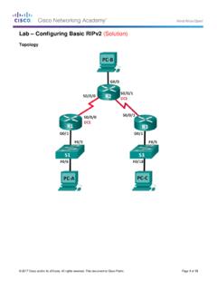
2 Set up a static MAC address. Background / Scenario Cisco switches can be configured with a special IP address known as the Switch virtual interface (SVI). The SVI, or management address, can be used for remote access to the Switch to display or configure Settings . If the VLAN 1 SVI is assigned an IP address, by default all ports in VLAN 1 have access to the SVI IP address. In this lab, you will build a simple topology using Ethernet LAN cabling and access a Cisco Switch using the console and remote access methods. You will examine default Switch configurations before Configuring Basic Switch Settings . These Basic Switch Settings include device name, interface description, local passwords, message of the day (MOTD) banner, IP addressing, and static MAC address. You will also demonstrate the Lab Configuring Basic Switch Settings 2017 Cisco and/or its affiliates.
3 All rights reserved. This document is Cisco Public. Page 2 of 16 use of a management IP address for remote Switch management. The topology consists of one Switch and one host using only Ethernet and console ports. Note: The Switch used is a Cisco Catalyst 2960 with Cisco IOS Release (2) (lanbasek9 image). Other switches and Cisco IOS versions can be used. Depending on the model and Cisco IOS version, the commands available and output produced might vary from what is shown in this lab. Note: Make sure that the Switch has been erased and has no startup configuration. Refer to Appendix A for the procedures to initialize and reload a Switch . Required Resources 1 Switch (Cisco 2960 with Cisco IOS Release (2) lanbasek9 image or comparable) 1 PC (Windows 7, Vista, or XP with terminal emulation program, such as Tera Term, and Telnet capability) 1 Console cable to configure the Cisco IOS device via the console port 1 Ethernet cable as shown in the topology Part 1: Cable the Network and Verify the Default Switch Configuration In Part 1, you will set up the network topology and verify default Switch Settings .
4 Step 1: Cable the network as shown in the topology. a. Connect the console cable as shown in the topology. Do not connect the PC-A Ethernet cable at this time. Note: If you are using Netlab, shut down F0/6 on S1. This has the same effect as not connecting PC-A to S1. b. Connect to the Switch from PC-A using Tera Term or other terminal emulation program. Why must you use a console connection to initially configure the Switch ? Why is it not possible to connect to the Switch via Telnet or SSH? _____ No IP addressing parameters are configured yet. A Cisco 2960 Switch first placed into service has no networking configured. Step 2: Verify the default Switch configuration. In this step, you will examine the default Switch Settings , such as current Switch configuration, IOS information, interface properties, VLAN information, and flash memory. You can access all the Switch IOS commands in privileged EXEC mode.
5 Access to privileged EXEC mode should be restricted by password protection to prevent unauthorized use because it provides direct access to global configuration mode and commands used to configure operating parameters. You will set passwords later in this lab. The privileged EXEC mode command set includes those commands contained in user EXEC mode, as well as the configure command through which access to the remaining command modes is gained. Use the enable command to enter privileged EXEC mode. a. Assuming the Switch had no configuration file stored in nonvolatile random-access memory (NVRAM), A console connection using Tera Term or other terminal emulation program will place you at the user EXEC mode prompt on the Switch with a prompt of Switch >. Use the enable command to enter privileged EXEC mode. Switch > enable Lab Configuring Basic Switch Settings 2017 Cisco and/or its affiliates.
6 All rights reserved. This document is Cisco Public. Page 3 of 16 Switch # Notice that the prompt changed in the configuration to reflect privileged EXEC mode. Verify that there is a clean default configuration file on the Switch by issuing the show running-config privileged EXEC mode command. If a configuration file was previously saved, it must be removed. Depending on the Switch model and IOS version, your configuration may look slightly different. However, there should be no configured passwords or IP address. If your Switch does not have a default configuration, erase and reload the Switch . Note: Appendix A details the steps to initialize and reload a Switch . b. Examine the current running configuration file. Switch # show running-config How many FastEthernet interfaces does a 2960 Switch have? _____ 24 How many Gigabit Ethernet interfaces does a 2960 Switch have?
7 _____ 2 What is the range of values shown for the vty lines? _____ 0-4 and 5-15 or 0-15 c. Examine the startup configuration file in NVRAM. Switch # show startup-config startup-config is not present Why does this message appear? _____ No configurations have been saved to NVRAM. d. Examine the characteristics of the SVI for VLAN 1. Switch # show interface vlan1 Is there an IP address assigned to VLAN 1? _____ No What is the MAC address of this SVI? Answers will vary. _____ 0CD9:96E2:3D40 in this case. Is this interface up? _____ Cisco switches have the no shutdown command configured by default on VLAN 1, but VLAN 1 won t reach the up/up state until a port is assigned to it and this port is also up. If there is no port in the up state in VLAN 1, then the VLAN 1 interface will be up, line protocol down. By default, all ports are assigned initially to VLAN 1.
8 E. Examine the IP properties of the SVI VLAN 1. Switch # show ip interface vlan1 What output do you see? _____ _____ Vlan1 is up, line protocol is down Internet protocol processing disabled f. Connect an Ethernet cable from PC-A to port 6 on the Switch and examine the IP properties of the SVI VLAN 1. Allow time for the Switch and PC to negotiate duplex and speed parameters. Note: If you are using Netlab, enable interface F0/6 on S1. Switch # show ip interface vlan1 Lab Configuring Basic Switch Settings 2017 Cisco and/or its affiliates. All rights reserved. This document is Cisco Public. Page 4 of 16 What output do you see? _____ _____ Vlan1 is up, line protocol is up Internet protocol processing disabled g. Examine the Cisco IOS version information of the Switch . Switch # show version What is the Cisco IOS version that the Switch is running?
9 _____ Answers may vary. (2)SE3 What is the system image filename? _____ Answers may vary. What is the base MAC address of this Switch ? Answers will vary. _____ Answers will vary. 0C:D9:96:E2:3D:00. h. Examine the default properties of the FastEthernet interface used by PC-A. Switch # show interface f0/6 Is the interface up or down? _____ It should be up unless there is a cabling problem. What event would make an interface go up? _____ Connecting a host or other device What is the MAC address of the interface ? _____ 0CD9:96E2:3D06 (Varies) What is the speed and duplex setting of the interface ? _____ Full-duplex, 100Mb/s i. Examine the default VLAN Settings of the Switch . Switch # show vlan What is the default name of VLAN 1? _____ default Which ports are in VLAN 1? _____ all ports; F0/1 F0/24; G0/1, G0/2 Is VLAN 1 active? _____ Yes What type of VLAN is the default VLAN?
10 _____ enet (Ethernet) j. Examine flash memory. Issue one of the following commands to examine the contents of the flash directory. Switch # show flash Switch # dir flash: Files have a file extension, such as .bin, at the end of the filename. Directories do not have a file extension. What is the filename of the Cisco IOS image? _____ (may vary) Lab Configuring Basic Switch Settings 2017 Cisco and/or its affiliates. All rights reserved. This document is Cisco Public. Page 5 of 16 Part 2: Configure Basic Network Device Settings In Part 2, you will configure Basic Settings for the Switch and PC. Step 1: Configure Basic Switch Settings . a. Copy the following Basic configuration and paste it into S1 while in global configuration mode. no ip domain-lookup hostname S1 service password-encryption enable secret class banner motd # Unauthorized access is strictly prohibited.