Transcription of Lab - Configuring VLANs and Trunking (Solution)
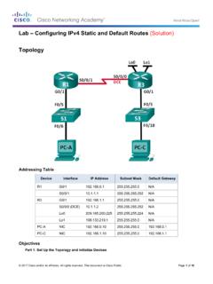
1 2013 Cisco and/or its affiliates. All rights reserved. This document is Cisco Public. Page 1 of 20 Lab - Configuring VLANs and Trunking (Solution) Topology Addressing Table Device Interface IP Address Subnet Mask Default Gateway S1 VLAN 1 N/A S2 VLAN 1 N/A PC-A NIC PC-B NIC PC-C NIC Objectives Part 1: Build the Network and Configure Basic Device Settings Part 2: Create VLANs and Assign Switch Ports Part 3: Maintain VLAN Port Assignments and the VLAN Database Part 4: Configure an Trunk between the Switches Part 5: Delete the VLAN Database Background / Scenario Modern switches use virtual local-area networks ( VLANs ) to improve network performance by separating large Layer 2 broadcast domains into smaller ones. VLANs can also be used as a security measure by controlling which hosts can communicate. In general, VLANs make it easier to design a network to support the goals of an organization.
2 Lab - Configuring VLANs and Trunking 2013 Cisco and/or its affiliates. All rights reserved. This document is Cisco Public. Page 2 of 20 VLAN trunks are used to span VLANs across multiple devices. Trunks allow the traffic from multiple VLANs to travel over a single link, while keeping the VLAN identification and segmentation intact. In this lab, you will create VLANs on both switches in the topology, assign VLANs to switch access ports, verify that VLANs are working as expected, and then create a VLAN trunk between the two switches to allow hosts in the same VLAN to communicate through the trunk, regardless of which switch the host is actually attached to. Note: The switches used are Cisco Catalyst 2960s with Cisco IOS Release (2) (lanbasek9 image). Other switches and Cisco IOS versions can be used. Depending on the model and Cisco IOS version, the commands available and output produced might vary from what is shown in the labs.
3 Note: Ensure that the switches have been erased and have no startup configurations. If you are unsure contact your instructor. Required Resources 2 Switches (Cisco 2960 with Cisco IOS Release (2) lanbasek9 image or comparable) 3 PCs (Windows 7, Vista, or XP with terminal emulation program, such as Tera Term) Console cables to configure the Cisco IOS devices via the console ports Ethernet cables as shown in the topology Part 1: Build the Network and Configure Basic Device Settings In Part 1, you will set up the network topology and configure basic settings on the PC hosts and switches. Step 1: Cable the network as shown in the topology. Attach the devices as shown in the topology diagram, and cable as necessary. Step 2: Initialize and reload the switches as necessary. Step 3: Configure basic settings for each switch. a. Console into the switch and enter global configuration mode.
4 B. Copy the following basic configuration and paste it to the running-configuration on the switch. no ip domain-lookup service password-encryption enable secret class banner motd # Unauthorized access is strictly prohibited. # line con 0 password cisco login logging synchronous line vty 0 15 password cisco logging synchronous login exit c. Configure the host name as shown in the topology. Lab - Configuring VLANs and Trunking 2013 Cisco and/or its affiliates. All rights reserved. This document is Cisco Public. Page 3 of 20 d. Configure the IP address listed in the Addressing Table for VLAN 1 on the switch. e. Administratively deactivate all unused ports on the switch. f. Copy the running configuration to the startup configuration. Step 4: Configure PC hosts. Refer to the Addressing Table for PC host address information. Step 5: Test connectivity. Verify that the PC hosts can ping one another.
5 Note: It may be necessary to disable the PCs firewall to ping between PCs. Can PC-A ping PC-B? _____ Yes Can PC-A ping PC-C? _____ No Can PC-A ping S1? _____ No Can PC-B ping PC-C? _____ No Can PC-B ping S2? _____ No Can PC-C ping S2? _____ No Can S1 ping S2? _____ Yes If you answered no to any of the above questions, why were the pings unsuccessful? _____ _____ Pings were unsuccessful when trying to ping a device on a different subnet. For those pings to be successful, a default gateway must exist to route traffic from one subnet to another. Part 2: Create VLANs and Assign Switch Ports In Part 2, you will create student, faculty, and management VLANs on both switches. You will then assign the VLANs to the appropriate interface. The show vlan command is used to verify your configuration settings. Step 1: Create VLANs on the switches. a. Create the VLANs on S1. S1(config)# vlan 10 S1(config-vlan)# name Student S1(config-vlan)# vlan 20 S1(config-vlan)# name Faculty S1(config-vlan)# vlan 99 S1(config-vlan)# name Management S1(config-vlan)# end b.
6 Create the same VLANs on S2. c. Issue the show vlan command to view the list of VLANs on S1. S1# show vlan VLAN Name Status Ports Lab - Configuring VLANs and Trunking 2013 Cisco and/or its affiliates. All rights reserved. This document is Cisco Public. Page 4 of 20 ---- -------------------------------- --------- ------------------------------- 1 default active Fa0/1, Fa0/2, Fa0/3, Fa0/4 Fa0/5, Fa0/6, Fa0/7, Fa0/8 Fa0/9, Fa0/10, Fa0/11, Fa0/12 Fa0/13, Fa0/14, Fa0/15, Fa0/16 Fa0/17, Fa0/18, Fa0/19, Fa0/20 Fa0/21, Fa0/22, Fa0/23, Fa0/24 Gi0/1, Gi0/2 10 Student active 20 Faculty active 99 Management active 1002 fddi-default act/unsup 1003 token-ring-default act/unsup 1004 fddinet-default act/unsup 1005 trnet-default act/unsup VLAN Type SAID MTU Parent RingNo BridgeNo Stp BrdgMode Trans1 Trans2 ---- ----- ---------- ----- ------ ------ -------- ---- -------- ------ ------ 1 enet 100001 1500 - - - - - 0 0 10 enet 100010 1500 - - - - - 0 0 20 enet 100020 1500 - - - - - 0 0 99 enet 100099 1500 - - - - - 0 0 VLAN Type SAID MTU Parent RingNo BridgeNo Stp BrdgMode Trans1
7 Trans2 ---- ----- ---------- ----- ------ ------ -------- ---- -------- ------ ------ 1002 fddi 101002 1500 - - - - - 0 0 1003 tr 101003 1500 - - - - - 0 0 1004 fdnet 101004 1500 - - - ieee - 0 0 1005 trnet 101005 1500 - - - ibm - 0 0 Remote SPAN VLANs ---------------------------------------- -------------------------------------- Primary Secondary Type Ports ------- --------- ----------------- ---------------------------------------- -- What is the default VLAN? _____ VLAN 1 What ports are assigned to the default VLAN? _____ All switch ports are assigned to VLAN 1 by default. Step 2: Assign VLANs to the correct switch interfaces. a. Assign VLANs to the interfaces on S1. 1) Assign PC-A to the Student VLAN. S1(config)# interface f0/6 S1(config-if)# switchport mode access Lab - Configuring VLANs and Trunking 2013 Cisco and/or its affiliates.
8 All rights reserved. This document is Cisco Public. Page 5 of 20 S1(config-if)# switchport access vlan 10 2) Move the switch IP address VLAN 99. S1(config)# interface vlan 1 S1(config-if)# no ip address S1(config-if)# interface vlan 99 S1(config-if)# ip address S1(config-if)# end b. Issue the show vlan brief command and verify that the VLANs are assigned to the correct interfaces. S1# show vlan brief VLAN Name Status Ports ---- -------------------------------- --------- ------------------------------- 1 default active Fa0/1, Fa0/2, Fa0/3, Fa0/4 Fa0/5, Fa0/7, Fa0/8, Fa0/9 Fa0/10, Fa0/11, Fa0/12, Fa0/13 Fa0/14, Fa0/15, Fa0/16, Fa0/17 Fa0/18, Fa0/19, Fa0/20, Fa0/21 Fa0/22, Fa0/23, Fa0/24.
9 Gi0/1 Gi0/2 10 Student active Fa0/6 20 Faculty active 99 Management active 1002 fddi-default act/unsup 1003 token-ring-default act/unsup 1004 fddinet-default act/unsup 1005 trnet-default act/unsup c. Issue the show ip interface brief command. S1# show ip interface brief Interface IP-Address OK? Method Status Protocol Vlan1 unassigned YES unset up up Vlan99 YES manual up down FastEthernet0/1 unassigned YES unset up up FastEthernet0/2 unassigned YES unset administratively down down FastEthernet0/3 unassigned YES unset administratively down down FastEthernet0/4 unassigned YES unset administratively down down FastEthernet0/5 unassigned YES unset administratively down down FastEthernet0/6 unassigned YES unset up up FastEthernet0/7 unassigned YES unset administratively down down <output omitted> What is the status of VLAN 99?
10 Why? _____ The status of VLAN 99 is up/down, because it has not been assigned to an active port yet. d. Use the Topology to assign VLANs to the appropriate ports on S2. e. Remove the IP address for VLAN 1 on S2. Lab - Configuring VLANs and Trunking 2013 Cisco and/or its affiliates. All rights reserved. This document is Cisco Public. Page 6 of 20 f. Configure an IP address for VLAN 99 on S2 according to the Addressing Table. g. Use the show vlan brief command to verify that the VLANs are assigned to the correct interfaces. S2# show vlan brief VLAN Name Status Ports ---- -------------------------------- --------- ------------------------------- 1 default active Fa0/1, Fa0/2, Fa0/3, Fa0/4 Fa0/5, Fa0/6, Fa0/7, Fa0/8 Fa0/9, Fa0/10, Fa0/12, Fa0/13 Fa0/14, Fa0/15, Fa0/16, Fa0/17 Fa0/19, Fa0/20, Fa0/21, Fa0/22 Fa0/23, Fa0/24, Gi0/1.