Transcription of LAN Topologies - TechTarget
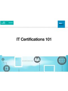
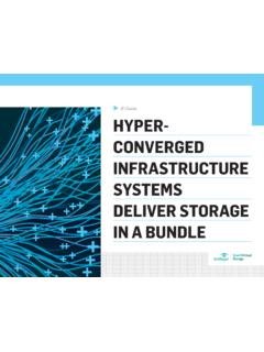
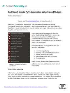
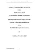
1 C H A P T E R2 LAN TopologiesThe application in use, such as multimedia, database updates, e-mail, or file and print sharing, generally determines the type of data transmissions fit into one of three categories: Unicast Multicast BroadcastUnicast With unicast transmissions, a single packet is sent from the source to a destination on a network. The source-node addresses the packet by using the network address of the destination node. The packet is then forwarded to the destination network and the network passes the packet to its final destination. Figure 2-1 is an example of a unicast 2-1 Unicast Page 13 Wednesday, November 14, 2001 3:28 PM14 Chapter 2: LAN TopologiesMulticastWith a multicast transmission, a single data packet is copied and forwarded to a specific subset of nodes on the network.
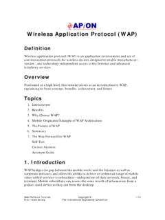
2 The source node addresses the packet by using a multicast address. For example, the TCP/IP suite uses to The packet is then sent to the network, which makes copies of the packet and sends a copy to each segment with a node that is part of the multicast address. Figure 2-2 is an example of a multicast 2-2 Multicast NetworkBroadcastBroadcasts are found in LAN environments. Broadcasts do not traverse a WAN unless the Layer 3 edge-routing device is configured with a helper address (or the like) to direct these broadcasts to a specified network address. This Layer 3 routing device acts as an interface between the local-area network (LAN) and the wide-area network (WAN). NOTEB roadcasts will traverse a WAN if the WAN is bridged.
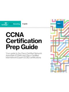
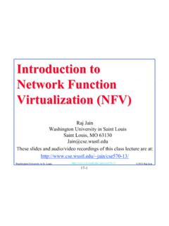
3 Page 14 Wednesday, November 14, 2001 3:28 PMBroadcast 15 NOTEE thernet is a broadcast environment in which one device transmits and all other devices see the transmission. Ethernet (broadcast) operation should not be confused with other LAN or WAN broadcasts, where the frame addressed to the broadcast address (a broadcast frame) is copied and forwarded across the network. Figure 2-3 is an example of a broadcast 2-3 Broadcast NetworkMultimedia broadcast traffic is a much more bandwidth-intensive broadcast traffic type. Multimedia broadcasts, unlike data broadcasts, typically are several megabits in size; therefore, they can quickly consume network and bandwidth resources. Broadcast-based protocols are not preferred because every network device on the network must expend CPU cycles to process each data frame and packet to determine if that device is the intended recipient.
4 Data broadcasts are necessary in a LAN environment, but they have minimal impact because the data broadcast frames that are traversing the network are typically small. Broadcast storms can cripple a network in no time because the broadcasting device uses whatever available bandwidth is on the example of a data broadcast on a LAN could be a host searching for server resources, such as Novell s IPX GNS (Get Nearest Server) or AppleTalk s Chooser data broadcasts, which are usually made up of small frames, multimedia broadcasts are typically several megabits in size. As a result, multimedia broadcasts can quickly consume all available bandwidth on a network, bringing a network and its attached devices to a crawl, if not render them Page 15 Wednesday, November 14, 2001 3:28 PM16 Chapter 2: LAN TopologiesTable 2-1 demonstrates the amount of bandwidth that multimedia applications can consume on a network.
5 For video-conferencing applications, 384 kilobits per second (Kbps) is the recommended maximum bandwidth for uncompressed data streams. Any bandwidth in excess of 384 Kbps typically will not be noticed by end users and could be considered a waste of bandwidth and in some cases, money. Table 2-2 shows multimedia bandwidth impact on a AddressingLAN (or any internetwork) addresses identify individual or groups of devices. Addressing schemes vary depending on the protocol family and OSI AddressesMedia Access Control (MAC) addresses identify network devices in LANs. MAC addresses are unique for each LAN interface on a device. MAC addresses are 48 bits in length and are expressed as 12 hexadecimal digits.
6 The first six hexadecimal digits, which are administered by the IEEE, identify the manufacturer or vendor and comprise the organizational unique identifier (OUI). The last six hexadecimal digits comprise the interface serial number, or another value administered by the specific vendor . MAC addresses are sometimes referred to as burned-in addresses (BIAs) because they are burned into read-only memory (ROM) and are copied into random-access memory (RAM) when the interface card 2-1 Multimedia Bandwidth Impact on a LAN ( Mbps* Stream)*Mbps = megabits per secondLink TypeFull-Screen, Full-Motion Client/Server Connections Supported ( Mbps Stream)10 Mbps6 to 7100 Mbps50 to 601000 Mbps250 to 300 Table 2-2 Multimedia Bandwidth Impact on a LAN (384 Kbps Stream)Link TypeFull-Screen, Full-Motion Client/Server Connections Supported (384 Kbps Stream)10 Mbps24 to 28100 Mbps200 to 2401000 Mbps1,000 to 1, Page 16 Wednesday, November 14, 2001 3.
7 28 PMLAN Topologies 17 MAC addresses are supported at the data link layer of the OSI model. According to the IEEE s specifications, Layer 2 comprises two components: the MAC sublayer and the logical link control (LLC) sublayer. The MAC sublayer interfaces with the physical layer (OSI model Layer 1), and the LLC sublayer interfaces with the network layer (OSI model Layer 3). Network Layer Addresses Network layer addresses identify a device at the OSI network layer (Layer 3). Network addresses exist within a hierarchical address space and sometimes are called virtual or logical layer addresses have two parts: the network of which the device is a part and the device, or host, number of that device on that network.
8 Devices on the same logical network must have addresses with the same network part; however, they will have unique device parts, such as network and host addresses in an IP or IPX network. For example, an IP address is often expressed as a dotted decimal notation, such as Each x in the address indicates either a network or host number, demonstrated as The subnet mask determines where the network boundary ends and the host boundary begins. LAN TopologiesFour LAN Topologies exist: Star (Hub-and-Spoke) Ring Bus TreeStar (Hub-and-Spoke) TopologyAll stations are attached by cable to a central point, usually a wiring hub or other device operating in a similar different cable types can be used for this point-to-point link, such as shielded twisted-pair (STP), unshielded twisted-pair (UTP), and fiber-optic cabling.
9 Wireless media can also be used for communications Page 17 Wednesday, November 14, 2001 3:28 PM18 Chapter 2: LAN TopologiesNOTESTP is not typically used in a point-to-point configuration. STP is used primarily in the Token Ring environment, where the hubs are called MAUs or MSAUs and the connections from the NIC to the MAU are not really point-to-point. This is because there is a transmit and a receive side, and the transmission is one way. In fact, this is sometimes called a star-ring. The advantage of the star topology is that no cable segment is a single point of failure impacting the entire network. This allows for better management of the LAN. If one of the cables develops a problem, only that LAN-attached station is affected; all other stations remain operational.
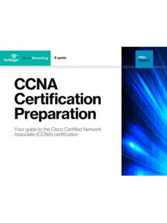
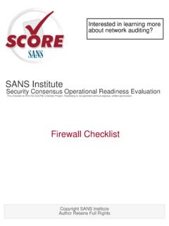
10 The disadvantage of a star (hub-and-spoke) topology is the central hub device. This central hub is a single point-of-failure in that if it fails, every attached station is out of central hubs, or concentrators, have changed over the years. Today, it is common to deploy hubs with built-in redundancy. Such redundancy is designed to isolate a faulty or failed component, such as the backplane or power supply. Figure 2-4 is an example of a star (hub-and-spoke) 2-4 Star (Hub-and-Spoke) TopologyThis example demonstrates a star topology with a file server, printer, and two workstations. If a cable to one of the workstations fails, the rest of the devices are unaffected unless they need to access resources from the disconnected device.