Transcription of LAPLACE TRANSFORMS AND ITS APPLICATIONS
1 LAPLACE TRANSFORMS AND ITS APPLICATIONSS arina AdhikariDepartment of Electrical Engineering and Computer Science, University of transform is a very powerful mathematical tool applied in various areas ofengineering and science. With the increasing complexity of engineering problems, LAPLACE transformshelp in solving complex problems with a very simple approach just like the APPLICATIONS of transferfunctions to solve ordinary differential equations. This paper will discuss the APPLICATIONS of Laplacetransforms in the area of physics followed by the application to electric circuit analysis. A morecomplex application on Load frequency control in the area of power systems engineering is INTRODUCTIONL aplace transform is an integral transform methodwhich is particularly useful in solving linear ordinary dif-ferential equations.
2 It finds very wide APPLICATIONS in var-ious areas of physics, electrical engineering, control engi-neering, optics, mathematics and signal processing. TheLaplace transform can be interpreted as a transforma-tion from the time domain where inputs and outputs arefunctions of time to the frequency domain where inputsand outputs are functions of complex angular order for any function of time f(t) to be Laplacetransformable, it must satisfy the following Dirichlet con-ditions [1]: f(t) must be piecewise continuous which meansthat it must be single valued but can have a finitenumber of finite isolated discontinuities fort >0. f(t) must be exponential order which means thatf(t) must remain less thanSe aotas t approaches whereSis a positive constant andaois a realpositive numberIf there is any functionf(t) that satisfies the Dirichletconditions, then,F(s) = 0f(t)e stdtwritten asL(f(t)) is called thelaplace transformation of f(t).
3 Here, s can be either areal variable or a complex integral f(t)e stdtconverges if |f(t)e st|dt < , s= +j A. Some Important Properties of LaplaceTransformsThe LAPLACE TRANSFORMS of different functions can befound in most of the mathematics and engineering booksand hence, is not included in this paper. Some of thevery important properties of LAPLACE TRANSFORMS whichwill be used in its APPLICATIONS to be discussed later onare described as follows:[1][2] LinearityThe LAPLACE transform of the linear sum of twoLaplace transformable functions f(t) + g(t) is givenbyL(f(t) +g(t)) =F(s) +G(s) DifferentiationIf the functionf(t) is piecewise continuous so thatit has a continuous derivativefn 1(t) of order n-1 and a sectionally continuous derivativefn(t) inevery finite interval 0 t T, then let,f(t) andall its derivatives throughfn 1(t) be of exponentialorderectast.
4 Then, the transform offn(t) exists whenRe(s)> cand has the following form:Lfn(t) =snF(s) sn 1f(0+) sn 2f(1)(0+) .. sn 1f(n 1)(0+) Time delayThe substitution oft for the variable t in thetransformLf(t) corresponds to the multiplicationof the functionF(s) bye s, that isL(f(t )) =e s F(s)II. APPLICATIONS OF LAPLACETRANSFORMSThis section describes the APPLICATIONS of Laplacetransforms in the areas of science and engineering. Atfirst, simple application in the area of Physics and Elec-tric Circuit theory is presented which will be followed bya more complex application to power system which in-cludes the description of Load Frequency Control (LFC)for transient stability Application in PhysicsA very simple application of LAPLACE transform in thearea of physics could be to find out the harmonic vibra-tion of a beam which is supported at its two ends [3].
5 Let us consider a beam of lengthland uniform crosssection parallel to the yz plane so that the normal de-flection w(x,t) is measured downward if the axis of thebeam is towards x axis. The basic equation defining thisphenomenon is as given below:2 EId4w/dx4 m 2w= 0; (1)where E is Young s modulus of elasticity; I is the mo-ment of inertia of the cross section with respect to the yaxis; m is the mass per unit length; and is the , rewriting the Eq(1) by setting 4=m 2w/EI,we obtain,d4 dx4 4 = 0.(2)Now, applying the LAPLACE transform to Eq(2),s4f(s) s3F(+0) s2F (+0) sF (+0) sF (+0) 4f(s) = boundary conditions for this problem are:F(+0) = 0;F(+l) = 0;F (+0) = 0;F (+l) = , we obtain,f(s) =s2F (+0) +F (+0)/s4 inverse LAPLACE transform gives, =F (+0)2 sinh x+ sin x+F (+0)2 3sinh x sin xThat is, =A1sinh x+A2sin ;A1sinh l+A2sin l= 0;A1sinh l A2sin l= 0;These are satisfied ifA1=A2= l=sin l= will give, l=n , for integral valuesof n.
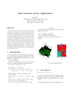
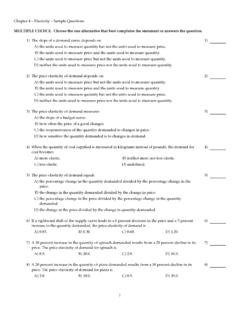
6 Hence,A1= 0 andA2is undetermined and theresulting vibrations are:wn=Ansin(n x/l) ,and the frequencies are n= 2n2l2 , ifn= 1, it represents the fundamental vibrationand ifn= 2 the first harmonic and so Application in Electric Circuit TheoryThe LAPLACE transform can be applied to solve theswitching transient phenomenon in the series or parallelRL,RC or RLC circuits [4]. A simple example of showingthis application follows us consider a series RLC circuit as shown in Fig which a voltageVois suddenly 1: Series RLC circuitNow, applying Kirchhoff s Voltage Law (KVL) to thecircuit, we have,Ri+Ldi/dt+ 1/C idt=Vo(3)Differentiating both sides,Ld2i/di2+ 1/Ci+Rdi/dt= 0;or, d2i/dt2+ (R/L)di/dt+ (1/LC)i= 0 (4)Now, applying LAPLACE transform to this equation, letus assume that the solution of this equation isi(t) =Kestwhere K and s are constants which maybe real, imaginary or , from eqn (4),LKs2est+RKest+ 1/CKest= 0 which on simplifica-tion gives,or, s2+ (R/L)s+ 1/LC= 0 The roots of this equation would bes1, s2=R/2L (R2/4L2) (1/LC)The general solution of the differential equation is thus,i(t) =K1es1t+K2es2twhereK1andK2are deter-mined from the intial , if we define, = Damping Coefficient =R/2 Land Natural Frequency, n= 1/ LCwhich is alsoknown as undamped natural frequency or resonant , roots are :s1, s2= 2 2nThe final form of solution depends on whether(R2/4L2)>1/LC.
7 (R2/4L2) = 1/LCand (R2/4L2)<1/LCThe three cases can be analysed based on the initialconditions of the circuit which are : overdamped case if > nCritically damped case if = nand under-damped case if < Application in Power Systems Load FrequencycontrolPower systems are comprised of generation, transmis-sion and distribution systems. A generating system con-sists of a turbogenerator set in which a turbine drives theelectrical generator and the generator serves the loadsthrough transmission and distribution lines. It is re-quired that the system voltage and frequency has to bemaintained at some pre-specified standards eg. frequencyhave to be maintained at 50 or 60 Hz and voltage mag-nitude should be per an interconnected power system, Load FrequencyControl (LFC) and Automatic Voltage Regulator (AVR)equipment are installed for each generator.
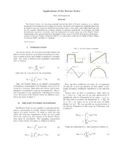
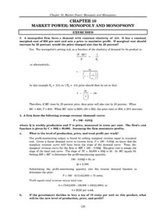
8 The con-trollers are set for a particular operating condition andtake care of small changes in load demand to maintain thefrequency and voltage within specified limits. Changes inreal power is dependent on the rotor angle, and thussystem frequency and the reactive power is dependent onthe voltage magnitude that is, the generator order to design the control system, the initial stepis the modeling of generator, load, prime mover (turbine)and governer [5].a. Generator ModelThe modeling of a generator by applying the swingequation of a synchronous machine [5]. When small per-3turbation is applied to the swing equation, the equationmodifies as follows:(2H/ s)(d2 /dt2) = Pm Pe(5)This can be written for a small deviation in speed withspeed expressed in per unit asd /dt= 1/2H( Pm Pe) (6)Now, applying LAPLACE transform to Eq(6), we obtain (s) = 1/2Hs[ Pm(s) Pe(s)] (7)This relation can be shown in the block diagram in 2: Generator block diagramb.
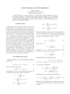
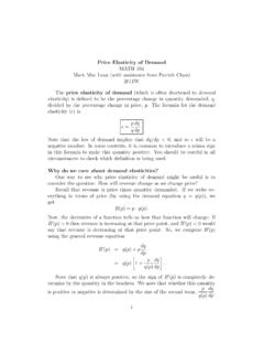
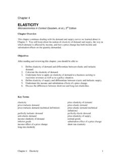
9 Load modelThe loads in the power system comprise of differentkinds of electrical devices. Some loads are frequency de-pendent such as motor loads and other loads like lightingand heating loads are independent of frequency. The fre-quency sensitivity of the loads depend on the speed loadcharacteristics of all the driven devices. The speed loadcharacteristic of a composite load is approximated by Pe= PL+D (8) where PLis the non fre-quency sensitive load change and D is the frequencysensitive load change. D is expressed as a percentagechange in load divided by percent change in combined block diagram representation of generatorand load is as shown in Fig 3: Generator and load block diagramc. Prime mover modelPrime mover is the source of mechanical power whichcan be hydraulic turbines or steam turbines.
10 The model-ing of the turbine is related to the change in mechanicalpower output Pmto the change in steam valve position Pv. The simplest prime mover model for a steam tur-bine can be developed by a single time constant, Tandhence, the resulting transfer function is as follows:GT(s) = Pm(s) PV(s)=11+ T(s)(9)The block diagram of a simple turbine is shown in 4: Prime mover block diagramd. Governer ModelDuring the cases when the generator load is suddenlyincreased, the electrical power exceeds the mechanicalpower input and this deficiency of power is supplied bythe kinetic energy stored in the rotating system. Dueto this reduction in kinetic energy, the turbine speed andhence, the generator frequency gets reduced. The turbinegoverner senses this reduction in speed and acts to adjustthe turbine input valve to change the mechanical poweroutput to bring the speed to a new steady 5: Governer speed characteristicsThe governers are designed to permit the speed to dropas the load is increased.