Transcription of LCL FILTERS - Circutor
1 LCL FILTERS INSTRUCTIONS MANUAL (M98121701-03-09A) (c) Circutor ------ LCL FILTERS : Instructions Manual ----- Page 2 2 TABLE OF CONTENTS TABLE OF CONTENTS 2 1 CHECKS ON RECEIPT OF THE EQUIPMENT. 3 2 INTRODUCTION. 3 3 OPERATING PRINCIPLE. 3 HOW TO SELECT A LCL FILTER? 3 4 TECHNICAL CHARACTERISTICS 4 GENERAL. 4 REACTORS 4 CAPACITORS 4 STANDARD types ( THREE PHASE 50HZ ) 5 OVERCOMPENSATION RELAY OPTION 5 DIMENSIONS AND WEIGHT 6 SCHEMATICS 8 5 INSTALLATION AND START-UP. 9 LOCATION. 9 INITIAL CHECKS (PRE-INSTALLATION, SWITCH THE POWER OFF). 9 CONNECTING THE POWER CIRCUIT.
2 (SEE SCHEMATICS IN FIG 3) 9 CONNECTING THE OPERATING CIRCUIT (ONLY IN CASE OF OVERCOMPENSATION PROTECTION) 9 START UP. 9 6 CHECK POINTS. 9 7 PERIODICAL SERVICING. 10 8 SAFETY. 10 9 TECHNICAL SERVICE AND GUARANTEE. 10 ------ LCL FILTERS : Instructions Manual ----- Page 3 3 1 CHECKS ON RECEIPT OF THE EQUIPMENT. Before installing and handling the equipment check that: 1) The equipment has not been damaged during delivery. 2) The equipment supplied is suitable for your requirements and is the type you ordered. 3) The operating voltage of the equipment supplied is suitable for your requirements. 4) Manuals for the equipment and for the regulator are supplied with the capacitor bank.
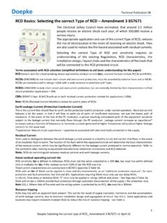
3 5) If any problem is noticed, please contact the commercial service department of Circutor 2 INTRODUCTION. LCL FILTERS are specially designed to reduce harmonics of current absorbed by power converters, with a rectifier input stage. (Frequency converters for motors, UPS, etc.). Mainly, they are made of a parallel-series combination of reactors and capacitors adapted to reduce the THD(I) of rectifiers. They are specially designed to reduce the THD(I) to values of approximately 8%, in order to comply with and IEEE-519 standards. 3 OPERATING PRINCIPLE. The structure of LCL FILTERS is as shown in the schematics below. The basic filter is designed with L1,L2, L3 and C.
4 In some cases reactor L4, is already placed in front of the converter. In such case L2 may be unnecessary M3 LCL FILTERMAINSIMPEDANCECONVERTERL1L2L3CL4 Fig. LCL FILTERS Structure How to select a LCL filter? LCL FILTERS must be selected according to the current absorbed by the converter. In case of converters with very low power rating, a unique LCL filter may be used to supply several converters, but only in case the all start and stop at the same time. If several converters starting and stopping separately are supplied by the same LCL filter, the system is not effective on filtering the harmonics. In such case an individual LCL should be used for each converter. ATTENTION: LCL FILTERS may produce cos overcompensation in case that the converter is absorbing a current much lower than the rated current of the filter itself.
5 This can be avoided by disconnecting the parallel LC circuit when the current falls below a certain adjustable limit. An optional protection circuit, consisting of a CMM-96-MD and a contactor, may be added to perform this function, if requested in the order. ------ LCL FILTERS : Instructions Manual ----- Page 4 4 WARNING!!!: Due to the LCL filter performance mode, it is quite likely to find elevate harmonic distortion levels of voltage at the input of the speed drive (downstream to the filter output reactor (L2)). This voltage distortion should cause no malfunction of the speed drive to be filtered, but it is very much recommendable, in case that this power drive is taken the auxiliary voltage supply of the control system from the input of the drive, to take this auxiliary supply from the LCL input, that is, upstream to the filter input reactor (L1).
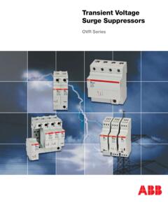
6 Fig. Mains supply without LCL filter Fig. Mains supply without LCL filter 4 TECHNICAL CHARACTERISTICS General. Standard voltage (phase to phase) 400V (Others on request) Frequency 50Hz for types LCL-35-xx or 60 Hz for types LCL-36-xx Rated load current See table of types Rated filtering current See table of types Parallel filter protection Fuses NH or NZ type depending on size residual THD Aprox. 8% Voltage drop at rated current < 2% Standards EN 60439, EN 60831 ; EN-50081-1, EN-50081-2 , class A Ambient temperature Ambient : 40 C Relative Humidity 80% Reactors Core / Coil High permeability metal sheet / Aluminium Isolation voltage 2kV Tolerance in L value <3% Saturation L=5% 1,6 of rated current Maximum ambient temperature 60 C Internal temperature at Irated <110 C Protection thermostat trip 90 C Total maximum overload ( )2 25% Permanent 20% Transient (1 min) 2 Irated Capacitors Dielectric Polypropylene Self-healing ------ LCL FILTERS .
7 Instructions Manual ----- Page 5 5 Working voltage < 1,15 of rated U Transient overload (10s) 1000 V Isolation voltage against earth 3 kV Operating temperature -25 / +50 C Losses 0,5W/kvar Standard types ( Three phase 50Hz ) TYPE (1) (3) RATED VOLTAGE (V ) RATED LOAD current (ARMS) RATED FILTERING current (ARMS) (2) CABINET MODEL LOSSES W LC L35-9A-400 400/415 9 3,6 A 55 LC L35-12A-400 400/415 12 4,8 A 73 LC L35-16A-400 400/415 16 6,4 A 97 LC L35-22A-400 400/415 22 8,8 A 134 LC L35-32A-400 400/415 32 12,8 A 194 LC L35-40A-400 400/415 40 16 A 243 LC L35-47A-400 400/415 47 18,8 B 286 LC L35-54A-400 400/415 54 21,6 B 328 LC L35-64A-400 400/415 64 25,6 B 389 LC L35-76A-400 400/415 76 30.
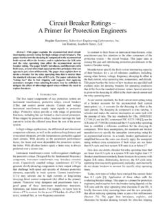
8 4 B 462 LC L35-90A-400 400/415 90 36 B 547 LC L35-110A-400 400/415 110 44 C 668 LC L35-150A-400 400/415 150 60 C 911 LC L35-180A-400 400/415 180 72 C 1094 LC L35-220A-400 400/415 220 88 D 1337 LC L35-260A-400 400/415 260 104 D 1580 LC L35-320A-400 400/415 320 128 D 1944 LC L35-400A-400 400/415 400 160 D 2430 REMARKS 1) If protection against power factor overcompensation is desired, specify in the order 2) Load is supposed to be a three phase 6 pulse rectifier, with dominant harmonics of order 5 and 7 3) For 60 Hz types , specify LCL36 instead of LCL35 Overcompensation relay option Measuring instrument CMM-96-MD Contactor suitable for the filter power current transformer TP type ------ LCL FILTERS : Instructions Manual ----- Page 6 6 Dimensions A - Sizes from 9 to 40 A IP21 B - Sizes from 47 to 90 A IP21 C Sizes from 110 to 180 A IP21 ------ LCL FILTERS : Instructions Manual ----- Page 7 7 D Sizes from 220 to 400 A IP21 ------ LCL FILTERS .
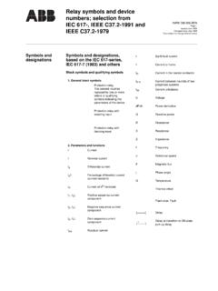
9 Instructions Manual ----- Page 8 8 SCHEMATICS U1V1W1 CTU2V2W2L1L2L3 NNCMM96-MDS1S2A1A2 LOADSIDES1S21518A1A2 MAINSSIDEM ains Switch mustbe placed upstreamL1L2L3CF1 Fig. Schematic drawing ------ LCL FILTERS : Instructions Manual ----- Page 9 9 5 INSTALLATION AND START-UP. Location. The equipment must be located indoors, away from heat sources and adequately ventilated. Initial checks (pre-installation, switch the power OFF). A main switch must be provided upstream to cut the supply of the filter. Check that the nominal voltage of the equipment, shown on the technical information label is the same as the nominal voltage between phases for the system to which it will be connected.
10 Connect the protective conductor: the cabinet must be earthed through the earthing terminal. Check and tighten terminals that may have come loose during delivery. Connecting the power circuit. (see schematics in Fig 3) Connect the power terminals (U1, V1, W1) to input cables coming from the mains side and (U2, V2, W2) to the cables going to the converter side. WARNING! If holes need to be drilled in the casing to feed cables through, take care to avoid shavings falling onto the contactors. Connecting the operating circuit (Only in case of overcompensation protection) The current transformer is installed at a point upstream of the filter.