Transcription of Lead-Free Selective Soldering: The Wave of the Future
1 Page 1 Lead-Free Selective soldering : the wave of the Future By Bob Klenke, ERSA, Inc. The European perspective on waste management and recycling as described in the European Union s Waste of Electrical and Electronic Equipment (WEEE) and Restriction of Hazardous Substances (ROS) strongly suggests that Lead-Free electronic assemblies will be mandatory in Europe by 2008. Japan is moving toward voluntary compliance by 2003 with a Lead-Free initiative that focuses on environmental marketing of new products such as mobile phones, consumer electronics and automotive electronics (with the exception of recycled lead-acid storage batteries). The viewpoint concerning Lead-Free electronic assemblies in the is somewhat different since lead usage in electronic solder comprises less than of total lead consumption.
2 Despite this fact, technological obsolescence of end-of-life (EOL) electronic products resulted in 21 million used computers being dumped into the solid-waste recycling process in additional concern is that although the electronic solder contained in electronic products represents less than of total lead consumption, of all lead bearing materials going into municipal solid waste (MSW) in the is from associated cathode ray tubes (CRT s) contained in television sets and computer monitors. If lead-acid storage batteries could be 100% recycled and thereby removed from MSW, electronic solder and CRT s would represent more than of the remaining lead bearing source Lead-Free REQUIREMENTS Lead-Free soldering of surface mount technology (SMT) has been studied extensively over the past several years while Lead-Free flow soldering of through hole (TH) components has received little attention.
3 However, in order for an electronic assembly to be considered as truly Lead-Free , every step of the assembly process must utilize Lead-Free materials including SMT reflow, TH soldering , rework, field repair and EOL recycling Wetting balance tests can be used to determine the solderability of any solder alloy. Wetting is an essential prerequisite for flow soldering of TH components, either by wave soldering or site-specific Selective soldering , and is a function of fluxing, preheating, solder temperature, contact time, wave formation and nitrogen inerting. Alloy Selection Lead-Free solder joints have been proven to be reliable based on a comprehensive series of accelerated thermal cycling (ATC) and failure analysis However, the majority of Lead-Free alloys available for TH flow soldering exhibit poorer properties and higher surface tension than traditional SnPb alloys which requires that they be processed at higher temperatures as shown in Table 1.
4 Alloy Melting Point Advantages Concerns 227 C Lower cost Higher temperatures 221 C Better thermal fatigue Silver toxicity 217 C Higher tensile strength Silver toxicity SnAgCuSb 217 C Increased reliability Toxicity and four part alloy Table 1: Comparison of Lead-Free Flow Solder Alloys This is especially true when flow soldering TH components on more challenging printed circuit boards (PCBs) that have a high thermal demand due to either complex ground planes, heat sinks or inter-layers. Page 2 The intermetallic compound layers formed by the majority of Lead-Free solder alloys during soldering and subsequent aging are similar to those present with equivalent SnPb The difference being that Lead-Free alloys do not contain a lead-rich region between the solder and the intermetallic layer that is typical with a lead bearing alloy after aging.
5 Intermetallic compound growth rates are statistically no different from those of traditional SnPb alloys. Flux Requirements Since the wetting characteristics of Lead-Free alloys are less than that typically exhibited by SnPb alloys at lower process temperatures, the selection of a good flux is mandatory to assure good solderability. The flux selected must be able to withstand exposure to the higher process temperatures required for Lead-Free alloys. In general, fluxes used for Lead-Free TH flow soldering must be able to withstand topside PCB preheat temperatures as high as 130C and solder temperatures as high as 280C for a minimum of 3 seconds of contact time or longer.
6 The major difference between SbPb and Lead-Free flow soldering is the higher melting point required by the Lead-Free alloy. Because Lead-Free alloys require higher preheat temperatures, thermal shocking of components as they enter the liquidous wave should not exceed 100C. For most applications, VOC- free , water-based fluxes, applied with a spray fluxer or inkjet drop fluxer, are recommended since they can withstand these higher processing temperatures. Thermal Aspects In order to form quality solder joints, the flow soldering process irregardless whether wave soldering or site-specific Selective soldering is used, must: 1) raise the temperature of the base metals high enough to allow sufficient wetting, 2) provide adequate contact time for capillary action to take place, and 3) provide adequate thermal energy to create an intermetallic layer.
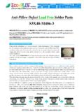
7 While Lead-Free solder alloys require higher processing temperatures due to the nature of their wetting properties, TH components can be damaged if their internal threshold temperature is exceeded by either rapid heating or excessive heating of the PCB assembly during the soldering This is especially true in Lead-Free flow soldering since the process temperatures are typically 30-40C higher than traditional SnPb alloy process temperatures for which most TH components were designed. Figure 1 shows a typical thermal process window for a TH component in which a minimum dwell time is required to promote wetting of the through-hole component lead while a maximum dwell time should not be exceeded that could result in damage to the component.
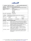
8 Likewise, a minimum temperature is required to make the solder liquidous while exceeding a maximum temperature could cause internal damage to the component. Figure 1: Processing Temperatures Page 3 The significant difference between SnPb and Lead-Free flow soldering thermal profiles are the increased preheat and solder temperatures shown in Figure 2. For most Lead-Free flow soldering applications, the topside PCB temperature will increase by as much as 125% to approximately 110-130C to limit the thermal shock as the PCB contacts the higher temperature of the Lead-Free liquidous solder. The ideal method is to heat up the PCB as quickly as possible to 100C and continue to heat the PCB with forced hot-air convection preheating for optimal evaporation of the water medium from the water-based This method of sustained preheat is also recommended for high-volume production or when soldering thermally challenged PCB assemblies.
9 Figure 2: Preheat Temperatures Due to the higher melting point of Lead-Free alloys, the temperature of the solder pot will also increase to improve solderability and shorten contact times. For AgSnCu with a melting point of 217C, the solder pot temperature will be between 250-270C or as high as 260-280C for SnCu. Dross Formation Lead-Free alloys oxidize more rapidly than SnPb solder when the alloy is liquidous and at a high processing temperature. Dross is comprised of cells of solder metal enveloped by an oxide skin. A new oxide layer forms on a liquidous solder bath immediately after the oxide skin is removed. Oxides formed on Lead-Free alloys are more evident than SnPb solder since Lead-Free alloys contain as much as 95% tin content compared to only 63% for 63/37 SnPb solder.
10 This higher tin content results in a more rapid formation of tin oxides, in the presence of tin-oxygen (SnO) and (SnO2), while the higher solder bath temperature accelerates the oxidation process. The behavior of tin oxide is predicable with SnPb solder in that the oxide layer breaks up easily and allows for straightforward removal of the dross. The oxide layer formed by a SnAg or SnAgCu Lead-Free alloy is more tenacious and does not break up into smaller particles making dross removal more difficult. The use of nitrogen inerting is highly recommended when implementing Lead-Free flow soldering since it not only improves wetting, but also minimizes the formation of tin oxide and dross.