Search results with tag "Jtag"
ATMEGA16U2 - Arduino
content.arduino.ccCard Interface) SSC (Synchronous Serial Controller) A11 A13 A22 D1 D3 D5 D7 D14 D12 NWR1/NBS1 NANDCLE NANDOE External Memory BUS SMC (Static Memory Controller) NFC (NAND Flash PA14 PD0 PD2 PD6 PA7 ... JTAG 1 +3V3 2 JTAG_TMS/SWDIO 3 GND 4 JTAG_TCK/SWCLK 5 GND 6 JTAG_TDO/TRACESWO 7 8 JTAG_TDI JTAG_RESET 9 GND …

Training JTAG Interface - Lauterbach
www2.lauterbach.com©1989-2021 Lau terbach GmbH Training JTAG Interface | 6 JTAG Basics JTAG is the name used for the IEEE 1149.1 standard entitled Standard Test Access Port and Boundary- Scan Architecture for test access ports (TAP) used for testing printed circuit boards (PCB) using boundary scan. JTAG is the acronym for Joint Test Action Group, the name of the group of …

UM1075 User manual - STMicroelectronics
www.st.com• JTAG/serial wire debugging (SWD) specific features – 1.65 V to 3.6 V application voltage suppo rted on the JTAG/SWD interface and 5 V tolerant inputs – JTAG cable for connection to a standard JTAG 20-pin pitch 2.54 mm connector – Supports JTAG communication – Supports serial wire debug (SWD) and serial wire viewer (SWV) communication
ARM JTAG Interface Specifications - Lauterbach
www2.lauterbach.com©1989-2021 Lau terbach GmbH ARM JTAG Interface Specifications | 5 Signals This JTAG interface is a superset of IEEE Std 1149.1. TCK, TMS, TDI, TDO, TRST- are the standard JTAG signals. A few more signals are added for advanced debug capabilities.

IEEE P1687 Internal JTAG (IJTAG) Tutorial
www.circuitnet.comThe goal of IEEE P1687 Internal JTAG (IJTAG) is to streamline the use of instruments that have been embedded in chips. The intent is to facilitate the deployment of these embedded instruments in a wider array of chip, board and system level validation, test and debug applications.

The Atmel-ICE Debugger - Microchip Technology
ww1.microchip.commicrocontrollers on both JTAG and aWire interfaces • Programming and on-chip debugging of all Atmel AVR XMEGA® family devices on both JTAG and PDI 2-wire interfaces • Programming (JTAG, SPI, UPDI) and debugging of all Atmel AVR 8-bit microcontrollers with OCD support on either JTAG, debugWIRE or UPDI interfaces

ZedBoard HW Users Guide
zedboard.orgJan 27, 2014 · Cascaded JTAG SD Card • Memory o 512 MB DDR3 (128M x 32) o 256 Mb QSPI Flash • Interfaces o USB-JTAG Programming using Digilent SMT1-equivalent circuit Accesses PL JTAG PS JTAG pins connected through PS Pmod o 10/100/1G Ethernet o USB OTG 2.0 o SD Card o USB 2.0 FS USB-UART bridge
The Atmel-ICE Debugger - Microchip Technology
ww1.microchip.commicrocontrollers on both JTAG and aWire interfaces • Programming and on-chip debugging of all Atmel AVR XMEGA® family devices on both JTAG and PDI 2-wire interfaces • Programming (JTAG, SPI, UPDI) and debugging of all Atmel AVR 8-bit microcontrollers with OCD support on either JTAG, debugWIRE or UPDI interfaces

J-Link ソフトウエア - エンビテック
www.embitek.co.jp2. jtag/swd コネクタ 2.1. jtagモードの接続仕様(20pin) ピン 信号 タイプ 説明 1 vtref 入力 ターゲットの基準電圧: jtag接続前に、ターゲット側の入力電圧の確認のために使用され ます。また、入力コンパレータのロジックレベルの参照を作成する
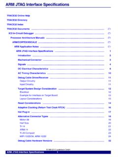
ARM JTAG Interface Specifications - Lauterbach
www2.lauterbach.comARM JTAG Interface Specifications 4 Signals ©1989-2015 Lauterbach GmbH Signals This JTAG interface is a superset of IEEE Std 1149.1.
Training JTAG Interface - Lauterbach
www2.lauterbach.comTraining JTAG Interface 6 ©1989-2018 Lauterbach GmbH Main Concept JTAG is defined as a serial communication protocol and a state machine accessible via a TAP.
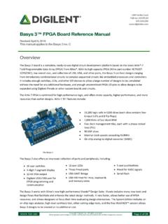
Basys 3™ FPGA Board Reference Manual - Digilent Reference
digilent.comJTAG programming can be done using the hardware server in Vivado. The demonstration project available at digilentinc.com provides an in-depth tutorial on how to program your board. 2.2 JTAG Programming When programming a nonvolatile flash device, a bitstream file is transferred to the flash in a two-step process. ...

XDS110 Debug Probe - Texas Instruments
www.ti.com– IEEE 1149.1 JTAG – IEEE 1149.7 cJTAG – ARM serial wire debug (SWD) – ARM serial wire output (SWO) – UART mode only – Transmit and receive UARTs with RS-232C signaling – no hardware handshakes 2.2 USB Host to probe communication is accomplished through a USB link. The probe has a female micro-USB B type connector.

特集JTAGってどう使う? 第1章 JTAGとは何か
www.cqpub.co.jp20 Design Wave Magazine 2000 February outline package)などの表面実装周辺端子型のパッケージが 実用化され,ピン間が狭くなるのに伴って,従来のプローブ

2.2.1 JTAGケーブルの接続 - kmckk.co.jp
www.kmckk.co.jp22 ターゲットシステムとの接続 kdoc041217 (1) ターゲットボード上に用意するjtagコネクタ(etm非対応) 14ピンおよび20ピンタイプコネクタを使用する場合の推奨回路図は以下のとおりで …

ADSP-SC589 EZ-Board® Evaluation System Manual
www.analog.com3.6.20 JTAG Connector (P3) 46 3.6.21 TRACE and JTAG Connector (P7) 46
FG Technology BDM - JTAG Driver list July 2018
www.fgtechnology.itFG Technology BDM - JTAG Driver list July 2018 - BDM Micro MC32xxx
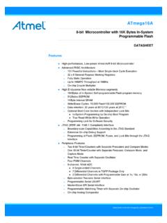
ATmega16A - Microchip Technology
ww1.microchip.comIf the JTAG interface is enabled, the pull-up resistors on pins PC5(TDI), PC3(TMS) and PC2(TCK) will be activated even if a reset occurs. Port C also serves the functions of the JTAG interface an d other special features of the ATmega16A as listed on page 59. 2.2.6 Port D …

ATDH1150USB - Microchip Technology
ww1.microchip.comAtmel-8909A-CPLD-ATDH1150USB-ATF15-JTAG-ISP-Download-Cable-UserGuide_072015 Introduction The Atmel® ATF15xx Complex Programmable Logic Device (CPLD) USB-based JTAG ISP Download Cable [Atmel PN: ATDH1150USB] connects to a standard USB port on a host computer on one side
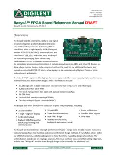
Basys3 ™ FPGA Board Reference Manual - Xilinx
www.xilinx.comJTAG programming can be done using the hardware server in Vivado. The demonstration project available at digilentinc.com provides an in depth tutorial on how to program your board. 2.2 Quad-SPI Programming When programming a nonvolatile flash device, a bitstream file is transferred to the flash in a two-step process. ...

stm32
riptutorial.comenvironment with JTAG Flash download and debug Active Rowley SW development suites DS-5 ARM Development Studio 5 (DS-5) provides best-in-class tools for the broadest range of ARM processor-based platforms Active ARM SW development suites Emprog ThunderBench, fully integrated and well-
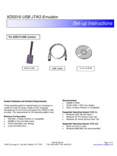
XDS510 USB JTAG Emulator - Spectrum Digital
emulators.spectrumdigital.comDriver CD ROM System Hardware and Software Requirements These operating platform requirements are necessary to install the Code Composer Studio (CCS) integrated

Platform Flash In-System Programmable Configuration …
www.xilinx.comJTAG Interface Memory OSC Serial or Parallel Decompressor DS123_19_031908. Platform Flash In-System Programmable Configuration PROMs DS123 (v2.19) June 6, 2016 www.xilinx.com Product Specification 3 R See UG161, Platform Flash PROM User Guide, for detailed guidelines on PROM-to-FPGA configuration hardware
STM32デバッグのための ICE・コネクタガイド
www.iar.comCortex-MのCoreSightテクノロジ 名称 接続 ICE 基本機能 特徴 JTAG I-jet I-jet Trace ST-LINK ・ディジーチェーン可能 ・(低速)printfデバッグ SWD I-jet I-jet Trace

AN0062: Programming Internal Flash Over the Serial Wire ...
www.silabs.com1 Debug Interface Overview 1.1 Serial Wire Debug Serial Wire Debug (SWD) is a two-wire protocol for accessing the ARM debug interface. It is part of the ARM Debug Interface Specification v5 and is an alternative to JTAG. The physical layer of SWD consists of two lines: • SWDIO: a bidirectional data line • SWCLK: a clock driven by the host

VC707 EVALUATION PLATFORM HW-V7-VC707 D …
www.xilinx.comSheet of Date: Title: Ver: A B C D 4 3 2 1 D C B A 4 3 2 1 Sheet Size: B Rev: Drawn By MECHANICALS SI570 VOLTAGE XLATOR Switching Module TDI TDO TDI TDO U1 FPGA TDI JTAG …

MSP430 Programming With the JTAG Interface …
www.ti.comRun-Test/IDLE Select DR-Scan Test-Logic-Reset 0 1 0 1 1 Fuse Check Power On Capture-DR Shift-DR Exit1-DR Pause-DR Exit2-DR Update-DR Select IR …

LIN Controller with Position Detection E521 - elmos.com
www.elmos.comLIN Controller with Position Detection E521.31 PRODUCTION DATA – Oct 6, 2015 Pin Description No Name Type Description 1 IO0 D_IO GPIO / JTAG TCK / PWM0 (internal pull-up)

Platform Cable USB II - Xilinx
www.xilinx.comInterface (SPI) flash memory devices Note: Direct SPI flash memory programming supported in Xilinx iMPACT software v10.1. † Indirectly programs selected SPI or parallel flash memory devices via FPGA JTAG port † Highly optimized for use with Xilinx design tools † Vivado® design tools or ISE® design tools † Embedded Development Kit
Report No: AN101 In-System Programming (ISP) of the Atmel ...
www.equinox-tech.comApplication Note 101 – SPI In-System Programming (ISP) Implementation for the Atmel AVR Microcontroller Family Version: V1.17 – 11th Feb 09 7 1.4 JTAG Algorithm Overview

A Primer: ARM Trace - SASE
www.sase.com.arA Primer: ARM® Trace Including: ETM™, ETB and Serial Wire Viewer, JTAG and SWD V 2.1
PM0075 Programming manual - STMicroelectronics
www.st.commicrocontroller using the JTAG protocol, the SWD protocol or the boot loader while the device is mounted on the user application board. I-Code: this bus connects the Instruction bus of the Cortex-M3 core to the Flash instruction interface. Prefetch is performed on this bus.

Debugger Basics - Training
www2.lauterbach.comTRACE32 Training ..... Debugger Training ... The most common on-chip debug interface is JTAG. A single on-chip debug interface can be used to debug all cores of a multi-core chip.
Altera DE0 Board - Intel
www.intel.comJTAG/AS Modes 16 x 2 LCD Interface Power ON/OFF Switch Triple 4 - bit VGA DAC PS/2 Port SD Card Socket RS - 232 Interface 50 - MHz Oscillator Power Supply Input USB Blaster Connector Altera EPCS 4 Configuration Device Figure 2.1. The DE0 board. The DE0 board has many features that allow the user to implement a wide range of designed
STM32 ST-LINK utility software description
www.st.comNote: The RESET pin of the JTAG connector (pin 15) must be connected to the device reset pin. The low-power mode is disabled when the user disconnects from the target. The ST-LINK firmware version to be used in case of multi probes selection must be: • V1J13S0 or greater for ST-LINK • V2J21S4 or greater for ST-LINK/V2

JTAG Introduction Programmer Guide
www.asc.ohio-state.edu• “JTAG Programmer Tutorial” chapter documents the basic tasks needed to download programming to XC9500/XL/XV family devices in-system. • “Designing Systems with FPGA's Enabled for Boundary-Scan Operations” chapter documents using the JTAG Programmer with FPGA devices. • “Boundary Scan Basics” appendix contains reference ...

JTAG Tutorial - Corelis
www.corelis.comlearned became formalized in an update to the core standard in 2001 and IEEE-1149.1-2001 was published. As new applications of JTAG were discovered, new standards were developed to extend the capabilities of JTAG. Standards such as the IEEE-1149.5 module test and maintenance bus standard in 1995 and the IEEE-1149.4 standard for mixed-signal
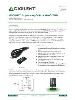
JTAG-HS3 Programming Cable for Xilinx FPGAs - Digilentinc
digilent.com1300 Henley Court Pullman, WA 99163 509.334.6306 www.digilentinc.com JTAG-HS3™ Programming Cable for Xilinx® FPGAs Revised March 13, 2019 This manual applies to the JTAG-HS3 rev. A
Similar queries
Interface, JTAG, UM1075 User manual, The JTAG, IEEE P1687 Internal JTAG (IJTAG) Tutorial, IEEE P1687 Internal JTAG IJTAG, The Atmel-ICE Debugger, ZedBoard HW, ARM JTAG Interface Specifications, JTAG Interface, Training JTAG, Basys 3, Tutorial, XDS110 Debug Probe, Texas Instruments, 1 JTAG, Kmckk, SC589 EZ-Board® Evaluation System Manual, Technology BDM - JTAG Driver list, ATmega16A, The JTAG Interface, ATDH1150USB, Xilinx, XDS510 USB JTAG Emulator, Platform, MSP430 Programming, Atmel AVR, A Primer, ARM Trace, ARM® Trace, PM0075 Programming manual, Training, TRACE32 Training, Intel, Programmer Guide, JTAG Tutorial, Core