Transcription of LIN Controller with Position Detection E521 - elmos.com
1 LIN Controller with Position Detection PRODUCTION DATA Oct 6, 2015 Features Integrated16 bit microcontroller 32kByte Flash 28kByte Flash for EEPROM-emulation, bootblock and up-time-counter 1 kByte RAM 4 PWM generator 16 bit: 16 bit resolution with fPWM,CYCLE up to 500Hz 2 timer + 2 capture compare timer 16bit ADC 12 bit resolution / fS=1 MHz 2 wire jtag debug interface (IAR compatible) Hardware divider / multiplier LIN-Bus transceiver ( ) including optional slave node Position Detection (SNPD) LIN UART with autobaud Detection < Voltage regulator / 100mA output Four LED highside driver (5V) Battery supply range 5V to 28 V Package QFN32L5 Applications Interior light modulesGeneral DescriptionThe device is a LIN Controller providing a 16bit microcontroller with two independent Flash memory blocks, a 5V voltage regulator with up to 100mA and a LIN transceiver providing optional auto integrated high side driver controlled by a 16 bit PWM can be used to drive external loads with current up to 50mA temperature compensation the device provides an integrated temperature InformationOrdering RangePackageE52131B61C-40 C to +125 CQFN32L5 Typical Operating CircuitElmos Semiconductor AG reserves the right to change the detail specifications as may be required to permit improvements in the design of its Semiconductor AGData SheetQM-No.
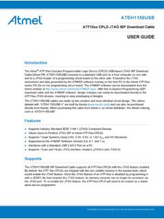
2 : 1 / 139 VDDIOO ptional jtag access portLIN_MGNDLIN_SVBATI nternalvoltageregulatorsLDO voltage regulator5V/100mA 2%uController32kByte FLASH1kByte RAM4x 16bit PWMT imerADC12bit1usLINUARTLIN transceiverwith VRWatchdogMUXOTXDRXDIN2IN1IN0IN3 VSGNDVDD3 VDDUCVDDCDGNDNRSTVDD5 OUT1 OUT2 OUT3 OUT4 LIM_MLIN_GNDLIN_SSIN4 SIN3 SIN2 SIN1IO5IO4IO3IO2IO1/TDAIO0/TCKTST LIN Controller with Position Detection PRODUCTION DATA Oct 6, 2015 Functional DiagramPin ConfigurationElmos Semiconductor AG reserves the right to change the detail specifications as may be required to permit improvements in the design of its Semiconductor AGData SheetQM-No.: 2 / 139 LIN Controller with Position Detection PRODUCTION DATA Oct 6, 2015 Pin DescriptionNoNameTypeDescription1IO0D_IO GPIO / jtag TCK / PWM0 (internal pull-up)2IO1D_IOGPIO / jtag TDA / PWM1 (internal pull-up)3IO2D_IOGPIO / TXD / CCTIMER MEAS / PWM2 (internal pull-up)4IO3D_IOGPIO / RXD / CCTIMER PWM / PWM3 / CLK_EXT (internal pull-up)5 NRSTD_InReset input (internal pull-up)6IO4D_IOGPIO / AIN1 (internal pull-down)7IO5D_IOGPIO / AIN2 (internal pull-down)8 TMODED_Itest mode (internal pull-down)9 VDDCS core voltage pad (internal regulator.)
3 10 DGNDSGND-Pin, IO ground pad, core ground pad11 AGNDSGND-Pin, analog ground analog supply input of uC, analog voltage pad ( ) voltage regulator for C part (up to 35mA)and VDDIO-supply voltage input pin of uC14 GNDHV_Sground15 VDD5 Speripheral voltage supply16 VSHV_Sbattery supply voltage17 OUT1A_Ohigh side driver for LED118 OUT2A_Ohigh side driver for LED219 OUT3A_Ohigh side driver for LED320 OUT4A_Ohigh side driver for LED421 SIN1A_Isense input 122 SIN2A_Isense input 223 SIN3A_Isense input 324 SIN4A_Isense input 425 LIN_GNDHV_SLIN ground26, bus line (direction to next slave)Optional: If auto addressing is not used keep pin open or connect to pin LIN_M28 LIN_MHV_A_IOLIN bus line (direction towards master)Note: A = Analog, D = Digital, S = Supply, I = Input, O = Output, B = Bidirectional, HV = High VoltageElmos Semiconductor AG reserves the right to change the detail specifications as may be required to permit improvements in the design of its Semiconductor AGData SheetQM-No.
4 : 3 / 139 LIN Controller with Position Detection PRODUCTION DATA Oct 6, 20151 Functional SafetyThe development of this product is based on a process according to an ISO/TS 16949 certified quality manage-ment system. Functional safety requirements according to ISO 26262 have not been submitted to Elmos and there-fore have not been considered for the development of this of functional safety requirements according to ISO 26262 will have a significant impact on the development process and the technical , in case functional safety requirements according to ISO 26262 are submitted, both parties have to agreeon a DIA (Development Interface Agreement) before start of Semiconductor AG reserves the right to change the detail specifications as may be required to permit improvements in the design of its Semiconductor AGData SheetQM-No.: 4 / 139 LIN Controller with Position Detection PRODUCTION DATA Oct 6, 20152 Absolute Maximum RatingsStresses beyond these absolute maximum ratings listed below may cause permanent damage to the device.
5 These are stress ratings only; operation of the device at these or any other conditions beyond those listed in the operational sections of this document is not implied. Exposure to absolute maximum rated conditions for extended periods may affect device reliability. All voltages referred to VGND. Currents flowing into terminals arepositive, those drawn out of a terminal are IO voltage maximum rating (pins, IO0, .. IO5, TMODE, NRST)continuousVIOx, + power supply and I/O voltagecontinuousVDDuC, voltage at pin VScontinuousVVS, temperaturecontinuousTJUNC-40125 C5 Storage temperaturecontinuous, unsolderedTSTG-40125 C6 Voltage at pins LIN_M, LIN_ScontinuousVLIN,x-2740V7DC current at each other pin, if not specified oth-erwisecontinuousIIO,LUP-1010mA8DC voltage at pin VScontinuousVS, voltage at pin VDD5continuousVDD, current at pin VDD5continuousIDD,DC-1501mA11DC voltage at pin VDD3continuousVVDD3, current at pin VDD3continuousIVDD3, and maximum voltage at pins OUT1-OUT4continuousVOUTx, at pins OUT1-OUT41)
6 ContinuousIOUTx, and maximum voltage at pins SIN1-SIN4continuousVSIN, Temperature RangeTABS-40150 C17 Analog Power Supply = Chip Core Power + of FLASH erase cyclesEndurance10000cycles21 FLASH data retention timeT = 85 CData_Retention10years22number of allowed "same address FLASH pro-gram cycles" before next eraseSame_Addr_Program2cycles23cumulativ e FLASH row program timeRow_Program_Time32ms1) The suppling VDD5 voltage regulator provides about 150mA to the HS-Drivers, although the all 4 drivers are able to handle 75mA each, the entire IC provides a sum current over all drivers of about 150mA peakElmos Semiconductor AG reserves the right to change the detail specifications as may be required to permit improvements in the design of its Semiconductor AGData SheetQM-No.: 5 / 139 LIN Controller with Position Detection PRODUCTION DATA Oct 6, 20153 ESD, Latch Up and Electro Static Discharge (ESD)StandardAEC-Q100-002 ModelHuman Body Model (HBM)Capacitance100 pFResistance1,5 k Minimum withstand Voltage+/- 8 kV for LIN to system groundMinimum withstand Voltage+/- 4 kV for VS to system groundMinimum withstand Voltage+/- 2 kV for all other pinsPulse rise time (10%-90%)< 10 nsTest pointpin to supplyNumber of pulses1 of each poarityStandardAEC-Q100-003 ModelMachine Model (MM)Test pointPin to system groundCapacitance200 pFResistance0 k Minimum withstand Voltage+/- 100 V for Pins VS, LIN_M, LIN_S to system groundStandardAEC-Q100-011 ModelCharged Device Model (CDM)Resistance1 Minimum withstand Voltage+/- 750 V for edge pins+/- 500 V for all other pinsPulse rise time (10%-90%)
7 <400 psOptional ESD TestTest equipment similar IEC 61000-4-2 Capacitance150pFResistance330 Minimum withstand Voltage+/- 8kV(According to document "OEM hardware requirements for LIN, CAN and FlexRay Interfaces", version ) Latch-upLatch-up performance is validated according JEDEC standard JESD 78 in its valid EMC The device needs to fulfil the OEM EMC requirements specified in the "Hardware Requirements for LIN, CAN and FlexRay Interfaces in Automotive Applications", , dated Semiconductor AG reserves the right to change the detail specifications as may be required to permit improvements in the design of its Semiconductor AGData SheetQM-No.: 6 / 139 LIN Controller with Position Detection PRODUCTION DATA Oct 6, 20154 Recommended Operating ConditionsDescriptionConditionSymbolMinTypMaxUnitfunctional range, besides LIN, LIN > 7 VVS, functional rangeVS,FL,HR1827 Vexternal load capacitance at pin VDD51)CVDD5, of external load capacitor CVDD5,LF at pin VDD52)ESRC_VDD5,LF-100500m External buffer capacitance range at pin VDD3 CVDD310100470nFESR of external buffer capacitor pin operating temperatureTOP-4025125 Cchip supply capacitance at VDDC pinCDDC71013nF1) this capacitor is mandatory for proper functioning of the IC2) this capacitor parameter is mandatory for proper functioning of the ICElmos Semiconductor AG reserves the right to change the detail specifications as may be required to permit improvements in the design of its Semiconductor AGData SheetQM-No.
8 : 7 / 139 LIN Controller with Position Detection PRODUCTION DATA Oct 6, 20155 Electrical Characteristics(VVS = to 27V, Tamb=-40 C to + 125 C, unless otherwise noted. Typical values are at VVS= and Tamb=+25 C. Positive currents flow into the device pins.)DescriptionConditionSymbolMinTypMa xUnituC analog Supply, pin VDDuCSupply and I/O voltage of the integrated micro- Controller *) Supply and References; pin VScurrent consumption in active modeLIN dominant, IDD=0mAIS,ACT,DOM--5mAcurrent consumption in active modeLIN recessive, IDD=0mAIS,ACT,REC--5mAsleep current at temperatures less than 40 Csleep mode,LIN recessive,VS =VLIN= <40 CIS,SLEEP_LT-915 Asleep current at temperatures higher than 40 Csleep mode,LIN recessive,VS =VLIN= >40 CIS,SLEEP_HT-1320 Apower on reset according to pin VSpower on thresholdVS, down threshold according to pin VSpower down thresholdVS, Regulator 5V; pin VDD5 Output voltage at pin VDD5active mode, VS > , IDD5 >= -100mA, -40 C <= TJUNC <= 125 programming range lower limit (5 Bit)active mode, VS > , IDD5 >= -100mA, -40 C <= TJUNC <= 125 C,CAL_5V = programming range upper limit (5 Bit)active mode, VS > 6V, IDD5 >= -100mA, -40 C <= TJUNC <= 125 C,CAL_5V = programming resolution*)active mode, VS > , IDD5 >= -100mA, -40 C <= TJUNC <= 125 CVDD5_RES-2650mV/LSBoutput current limitationIDD5,LIM-350--200mAElmos Semiconductor AG reserves the right to change the detail specifications as may be required to permit improvements in the design of its Semiconductor AGData SheetQM-No.
9 : 8 / 139 LIN Controller with Position Detection PRODUCTION DATA Oct 6, 2015 DescriptionConditionSymbolMinTypMaxUnitO utput Resistance of the VDD5 voltage regulator inthe LowDrop region*)active mode, <= VS <= VDD5 + ROUT5_LD*(-IDD5), IDD5 >= -100mA, -40 C <= TJUNC <= 125 Voltage Regulator ; pin VDD3 Output voltage at pin VDD35V <= VS <= 27V IDD3 >= current limitation5V <= VS <= 27 VIDD3,LIM-80--40mACharacteristicsfunctional range LIN transceiverVLIN,VS7-18 Vrecessive output voltageTXD = 1 VLIN,RECVS -1V-VS-dominant output voltageTXD = 0, VS = , RLIN = to VSVLIN, output voltageTXD = 0, VS = 18V, RLIN = to VSVLIN, dominant levelVLIN, recessive levelVLIN, bus center voltageVLIN,BUSCNT = (VLIN,THDOM + VLIN,THREC) / 2 VLIN, hysteresisVLIN,THREC - VLIN,THDOMVLIN, current limitationVLIN = VVS,MAX = 18 VILIN,LIM40-200mApull up resistanceRLIN, leakage current flowing into pin LINtransmitter pass-ive, 7V < VS < 18V, 7V < VLIN < 18V, VLIN > VSILIN,BUSREC--20 Apull up current flowing out of pin LINtransmitter pass-ive, 7V < VS < 18V, VLIN = 0 VILIN,BUSDOM-1--mAleakage current, ground disconnected (GND device = VS)VS = , 0V <VLIN < 18 VILIN, current, supply disconnectedVS = 0V, 0V < VLIN < 18 VILIN--20 Aclamping voltage *)
10 VS = 0V, ILIN = 1mAVLIN,CLAMP40-Vinput capacitance *)7V < VS < 18 VCLIN,PIN--30pFreceive propagation delaytRXD,PDR--6 sreceive propagation delay symmetrytRXD,SYM-2-2 sElmos Semiconductor AG reserves the right to change the detail specifications as may be required to permit improvements in the design of its Semiconductor AGData SheetQM-No.: 9 / 139 LIN Controller with Position Detection PRODUCTION DATA Oct 6, 2015 DescriptionConditionSymbolMinTypMaxUnitL IN bus pulse receiver debounce time*)tLIN, swake up debounce timetLIN,WU70-150 sDuty cycle 11)VLIN,THREC(max) = *VS, VLIN,THDOM(max) = *VS, VS = 7-18V, tBIT = 50us, DLIN,1 = tBUS-REC(min)/(2*tBIT)DLIN, cycle 21)VLIN,THREC(min) = *VS, VLIN,THDOM(min) = *VS, VS = 7-18V, tBIT = 50us, DLIN,2 = tBUS-REC(max)/(2*tBIT)DLIN, cycle 31)V,LIN,THREC(max) = *VS, VLIN,THDOM(max) = *VS, VS = 7-18V, tBIT = 96us, DLIN,3 = tBUS-REC(min)/(2*tBIT)DLIN, cycle 41)VLIN,THREC(min) = *VS, VLIN,THDOM(min) = *VS, VS = 7-18V, tBIT = 96us, DLIN,4 = tBUS-REC(max)/(2*tBIT)DLIN, data baud rate*)high speed mode,VS = ,RXD115kBd/stransmit data baud rate*)high speed mode,VS = ,TXD115kBd/sElmos Semiconductor AG reserves the right to change the detail specifications as may be required to permit improvements in the design of its Semiconductor AGData SheetQM-No.