Transcription of UM1075 User manual - STMicroelectronics
1 October 2018UM1075 Rev 81/191UM1075 user manualST-LINK/V2 in-circuit debugger/programmer for STM8 and STM32 IntroductionThe ST-LINK/V2 is an in-circuit debugger/programmer for the STM8 and STM32 microcontrollers. The single wire interface module (SWIM) and the jtag /serial wire debugging (SWD) interfaces facilitate the communication with any STM8 or STM32 microcontroller operating on an application addition to providing the same functionalities of the ST-LINK/V2, the ST-LINK/V2-ISOL features digital isolation between the PC and the target application board. It also withstands voltages of up to 1000 USB full-speed interface enables communication with a PC and: STM8 devices via ST Visual Develop (STVD) or ST Visual Program (STVP) software (available from STMicroelectronics ) STM32 devices via Atollic , IAR , Keil and TASKING integrated development 1. ST-LINK/V2 and ST-LINK/V2-ISOLST-LINK/V2ST- Rev 8 Contents1 Features.
2 52 Ordering information .. 53 Product contents .. 64 Hardware configuration .. with STM8 .. ERNI connection with SWIM flat ribbon .. SWIM connection .. signals and connections .. with STM32 .. status LED .. 145 Software configuration .. firmware upgrade .. application development .. application development and Flash programming .. 156 Schematics .. 167 Revision history .. 18UM1075 Rev 83/19UM1075 List of tables3 List of tablesTable of the order codes .. 5 Table flat ribbon connections for ST-LINK/V2 .. 11 Table low-cost cable connections for ST-LINK/V2-ISOL .. 11 Table cable connections .. 12 Table third-party toolchains support ST-LINK/V2 .. 15 Table revision history .. 18 List of figuresUM10754/19UM1075 Rev 8 List of figuresFigure and ST-LINK/V2-ISOL .. 1 Figure product contents .. 6 Figure product contents .. 7 Figure of the ST-LINK/V2 (on the left) and of the ST-LINK/V2-ISOL (on the right).
3 8 Figure connection .. 9 Figure detail on connectors .. 10 Figure connection .. 10 Figure SWIM connector .. 11 Figure and SWD connection .. 13 Figure debugging flat ribbon layout .. 13 Figure ST-LINK/V2 standard ERNI cable .. 16 Figure ST-LINK/V2 low-cost cable .. 17UM1075 Rev 85/19UM1075 Features181 Features 5 V power supplied by a USB connector USB full speed compatible interface USB standard A to Mini-B cable SWIM specific features V to V application voltage supported on SWIM interface SWIM low-speed and high-speed modes supported SWIM programming-speed rate: Kbytes/s in low speed and Kbytes/s in high speed SWIM cable for connection to the application via an ERNI standard vertical (ref: 284697 or 214017) or horizontal (ref: 214012) connector SWIM cable for connection to the application via a pin header or a mm pitch connector jtag /serial wire debugging (SWD) specific features V to V application voltage supported on the jtag /SWD interface and 5 V tolerant inputs jtag cable for connection to a standard jtag 20-pin pitch mm connector Supports jtag communication Supports serial wire debug (SWD) and serial wire viewer (SWV) communication Direct firmware update feature supported (DFU) Status LED, which blinks during communication with the PC 1000 VRMS high isolation voltage (ST-LINK/V2-ISOL only) Operating temperature from 0 to 50 C2 Ordering informationTo order the ST-LINK/V2 refer to Table 1.
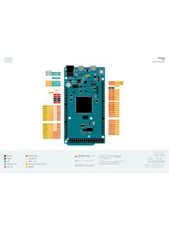
4 Table 1. List of the order codes Order codeST-LINK descriptionST-LINK/V2In-circuit debugger/programmerST-LINK/V2-ISOLIn-cir cuit debugger/programmer with digital isolationProduct contentsUM10756/19UM1075 Rev 83 Product contentsThe cables delivered within the product are shown in Figure 2 and Figure 3. They include (from left to right): USB standard A to Mini-B cable (A) ST-LINK/V2 debugging and programming (B) SWIM low-cost connector (C) SWIM flat ribbon with a standard ERNI connector at one end (D) jtag or SWD and SWV flat ribbon with a 20-pin connector (E)Figure 2. ST-LINK/V2 product contentsABCDEUM1075 Rev 87/19UM1075 Product contents18 Figure 3. ST-LINK/V2-ISOL product contentsABCDEH ardware configurationUM10758/19UM1075 Rev 84 Hardware configurationThe ST-LINK/V2 is designed around the STM32F103C8 device, which incorporates the high-performance Arm (a) Cortex -M3 core.
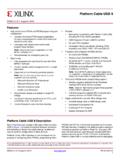
5 It is available in a TQFP48 shown in Figure 4, the ST-LINK/V2 provides two connectors: an STM32 connector for the jtag /SWD and SWV interface an STM8 connector for the SWIM interfaceThe ST-LINK/V2-ISOL provides one connector for the STM8 SWIM, STM32 jtag /SWD and SWV 4. Connectors of the ST-LINK/V2 (on the left) and of the ST-LINK/V2-ISOL (on the right)1. A = STM32 jtag and SWD target connector2. B = STM8 SWIM target connector3. C = STM8 SWIM, STM32 jtag and SWD target connector4. D = Communication activity LEDa. Arm is a registered trademark of Arm Limited (or its subsidiaries) in the US and/or Rev 89/19UM1075 Hardware Connection with STM8 For development of applications based on STM8 microcontrollers, the ST-LINK/V2 can be connected to the target board by two different cables, depending on the connector available on the application board. These cables are: SWIM flat ribbon with a standard ERNI connector at one end SWIM cable with two 4-pin, mm connector or SWIM separate-wires Standard ERNI connection with SWIM flat ribbonFigure 5 shows how to connect the ST-LINK/V2 if a standard ERNI 4-pin SWIM connector is present on the application board.
6 Figure 5. ERNI connection1. A = Target application board with ERNI connector2. B = Wire cable with ERNI connector at one end3. C = STM8 SWIM target connector4. See Figure 11 Figure 6 shows that pin 16 is missing on the ST-LINK/V2-ISOL target connector. This missing pin is used as a safety key on the cable connector, to guarantee connection of the SWIM cable in the correct position on the target connector even pins, used for both SWIM and jtag configurationUM107510/19UM1075 Rev 8 Figure 6. Key detail on Low-cost SWIM connectionFigure 7 shows how to connect the ST-LINK/V2 if a 4-pin, mm, low-cost SWIM connector is present on the application 7. Low-cost connection1. A = Target application board with 4-pin, mm, low-cost connector2. B = Wire cable with a 4-pin connector or separate-wires cable3. C = STM8 SWIM target connector4. See Figure SWIM signals and connectionsTa b l e 2 summarizes the signal names, functions, and target connection signals using the wire cable with a 4-pin Rev 811/19UM1075 Hardware configuration18 Figure 8.
7 Target SWIM connectorTa b l e 3 summarizes the signal names, functions, and target connection signals using the separate-wires the SWIM separate-wires cable has independent connectors for all pins on one side, it is possible to connect the ST-LINK/V2-ISOL to an application board without a standard SWIM connector. On this flat ribbon, all signals are referenced by a specific color and a label to ease the connection on target. TVCC, SWIM, GND and SWIM-RST can be connected to a low-cost mm pitch connector or to pin headers available on the target 2. SWIM flat ribbon connections for ST-LINK/V2 Pin connection1 VDDT arget VCC(1)1. The power supply from the application board is connected to the ST-LINK/V2 debugging and programming board to ensure signal compatibility between both VCC2 DATASWIMMCU SWIM pin3 GNDGROUNDGND4 RESETRESETMCU RESET pinTable 3. SWIM low-cost cable connections for ST-LINK/V2-ISOL ColorCable pin nameFunctionTarget connectionRedTVCCT arget VCC(1)1.
8 The power supply from the application board is connected to the ST-LINK/V2 debugging and programming board to ensure signal compatibility between both VCCG reenUART-RXUnusedReserved (2)(not connected on the target board)2. BOOT0, UART-TX and UART-RX are reserved for future l l o wB O O T 0 OrangeSWIMSWIMMCU SWIM pinBlackGNDGROUNDGNDW hiteSWIM-RSTRESETMCU RESET pinHardware configurationUM107512/19UM1075 Rev Connection with STM32 For development of applications based on STM32 microcontrollers the ST-LINK/V2 needs to be connected to the application using the standard 20-pin jtag flat ribbon b l e 4 summarizes the signals names, functions, and target connection signals of the standard 20-pin jtag flat ribbon. Table 4. jtag /SWD cable connections Pin connector (CN3)ST-LINK/V2functionTarget connection( jtag )Target connection(SWD)1 VAPPT arget VCC MCU VDD(1)1. The power supply from the application board is connected to the ST-LINK/V2 debugging and programming board to ensure signal compatibility between the VDD(1)23 TRSTJTAG TRSTJNTRSTGND(2)2.
9 Connect to GND for noise reduction on the (3)3. Available on ST-LINK/V2 only, not connected on ST- (3)GND(3)(4)4. At least one of this pin must be connected to the ground for correct behavior (connecting all of them is recommended).GND(3)(4)5 TDIJTAG TDOJTDIGND(2)6 GND(3)GND(3)GND(3)(4)GND(3)(4)7 TMS_SWDIOJTAG TMS, SW IOJTMSSWDIO8 GND(3)GND(3)GND(3)(4)GND(3)(4)9 TCK_SWCLKJTAG TCK, SW CLK JTCKSWCLK10 GND(5)5. GND on ST-LINK/V2, used by SWIM on ST-LINK/V2-ISOL (see Table 3).GND(5)GND(4)(5)GND(4)(5)11 Not connectedNot connectedNot connectedNot connected12 GND GNDGND(4)GND(4)13 TDO_SWOJTAG TDI, SWOJTDOTRACESWO(6)6. Optional: for Serial Wire Viewer (SWV) (5)GND(5)GND(4)(5)GND(4)(5)15 NRSTNRSTNRSTNRST16 GND(3)GND(3)GND(3)(4)GND(3)(4)17 Not connectedNot connectedNot connectedNot connected18 GNDGNDGND(4)GND(4)19 VDD(3)VDD ( V)(3)Not connectedNot connected20 GNDGNDGND(4)GND(4) UM1075 Rev 813/19UM1075 Hardware configuration18 Figure 9 shows how to connect the ST-LINK/V2 to a target using the jtag 9.
10 jtag and SWD connection1. A = Target application board with jtag connector2. B = jtag /SWD 20-wire flat cable3. C= STM32 jtag and SWD target connectorThe reference of the connector needed on the target application board is: 2x10C header wrapping 2x40C H3 (pitch ) - HED20 SCOTT 10. jtag debugging flat ribbon layoutNote:For low cost applications or when the standard 20-pin connector footprint is too big, it is possible to implement the Tag-Connect solution to save cost and space on the application board. The Tag-Connect adapter and cable provide a simple and reliable means of connecting ST-LINK/V2 or ST-LINK/V2-ISOL to the PCB without requiring a mating component on the application PCB. ABCABC 9 LHZHG IURP DERYH 3&% AI Hardware configurationUM107514/19UM1075 Rev 8 For more details on this solution and application-PCB-footprint information, visit references of components compatible with jtag and SWD interfaces are: a) TC2050-ARM2010 adapter (20-pin- to 10-pin- interface board) b) TC2050-IDC or TC2050-IDC-NL (No Legs) (10-pin cable)c) TC2050-CLIP retaining clip for use with TC2050-IDC-NL (optional) ST-LINK/V2 status LEDThe LED labeled COM on top of the ST-LINK/V2 shows the ST-LINK/V2 status (whatever the connection type).