Transcription of AN3155 Application note - st.com
1 October 2016 DocID17066 Rev 71/371AN3155 Application noteUSART protocol used in the STM32 bootloader IntroductionThis Application note describes the USART protocol used in the STM32 microcontroller bootloader, providing details on each supported document applies to STM32 products embedding any bootloader version, as specified in the Application note AN2606 STM32 system memory boot mode , available on These products are listed in Ta b l e 1, and are referred to as STM32 throughout the more information about the USART hardware resources and requirements for your device bootloader, refer to the already mentioned AN2606.
2 Table 1. Applicable productsTypeProduct seriesMicrocontrollersSTM32L0 SeriesSTM32L1 SeriesSTM32L4 SeriesSTM32F0 SeriesSTM32F1 SeriesSTM32F2 SeriesSTM32F3 SeriesSTM32F4 SeriesSTM32F7 Rev 7 Contents1 USART bootloader code sequence .. 52 Choosing the USARTx baud rate .. baud rate .. baud rate .. 63 Bootloader command set .. command .. Version & Read Protection Status command .. ID command .. Memory command .. command .. Memory command .. Memory command .. Erase Memory command.
3 Protect command .. Unprotect command .. Protect command .. Unprotect command .. 334 Bootloader protocol version evolution .. 355 Revision history .. 36 DocID17066 Rev 73/37AN3155 List of tables3 List of tablesTable products .. 1 Table bootloader commands .. 7 Table protocol versions .. 35 Table revision history .. 36 List of figuresAN31554/37 DocID17066 Rev 7 List of figuresFigure for STM32 with USART .. 5 Figure command: host side .. 8 Figure command: device side .. 9 Figure Version & Read Protection Status command: host side.
4 10 Figure Version & Read Protection Status command: device side.. 11 Figure ID command: host side .. 12 Figure ID command: device side.. 13 Figure Memory command: host side .. 14 Figure Memory command: device side .. 15 Figure command: host side .. 16 Figure command: device side .. 17 Figure Memory command: host side .. 19 Figure Memory command: device side.. 20 Figure Memory command: host side.. 22 Figure Memory command: device side .. 23 Figure Erase Memory command: host side .. 25 Figure Erase Memory command: device side.
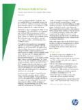
5 26 Figure Protect command: host side .. 28 Figure Protect command: device side .. 29 Figure Unprotect command: host side .. 30 Figure Unprotect command: device side .. 31 Figure Protect command: host side.. 32 Figure Protect command: device side .. 32 Figure Unprotect command: host side .. 33 Figure Unprotect command: device side .. 34 DocID17066 Rev 75/37AN3155 USART bootloader code sequence361 USART bootloader code sequenceFigure 1. Bootloader for STM32 with USARTOnce the system memory boot mode is entered and the STM32 microcontroller has been configured (for more details refer to AN2606) the bootloader code begins to scan the USARTx_RX line pin, waiting to receive the 0x7F data frame: one start bit, 0x7F data bits, even parity bit and one stop duration of this data frame is measured using the Systick timer.
6 The count value of the timer is then used to calculate the corresponding baud rate factor with respect to the current system , the code initializes the serial interface accordingly. Using this calculated baud rate, an acknowledge byte (0x79) is returned to the host, which signals that the STM32 is ready to receive commands. X & RECEIVED ON53!24X 2X PIN7 AIT FOR ACOMMAND'%4 CMDROUTINEAI 53!24X SELECTED!UTO BAUD RATE SEQUENCESEND !#+ BYTE DISABLEUNUSED PERIPHERALS2$ CMDROUTINE OPTIONAL 2 OUTINES FORLOADING INTO 2!-'/ CMDROUTINE*0 TO?
7 !DDRESS'/ CMD#OMMANDRECEIVED'%4 CMDC hoosing the USARTx baud rateAN31556/37 DocID17066 Rev 72 Choosing the USARTx baud rateThe calculation of the serial baud rate for USARTx, from the length of the first byte that is received, is used to operate the bootloader within a wide range of baud rates. However, the upper and lower limits have to be kept, in order to ensure proper data a correct data transfer from the host to the microcontroller, the maximum deviation between the internal initialized baud rate for USARTx and the real baud rate of the host should be below The deviation (fB, in percent) between the host baud rate and the microcontroller baud rate can be calculated using the formula below.
8 FBSTM32 baud rate Host baud rate STM32 baud rate------------------------------------ ---------------------------------------- ---------------100% =, where fB This baud rate deviation is a nonlinear function depending on the CPU clock and the baud rate of the host. The maximum of the function (fB) increases with the host baud rate. This is due to the smaller baud rate prescale factors, and the implied higher quantization Minimum baud rateThe lowest tested baud rate (BLow) is 1200. Baud rates below BLow would cause the SysTick timer to overflow.
9 In this event, USARTx would not be correctly Maximum baud rateBHigh is the highest baud rate for which the deviation still does not exceed the limit. All baud rates between BLow and BHigh are below the deviation limit. The highest tested baud rate (BHigh) is 115 Rev 77/37AN3155 Bootloader command set363 Bootloader command setThe supported commands are listed in Ta b l e 2 below. Each command is further described in this section. Communication safetyAll communications from the programming tool (PC) to the device are verified : received blocks of data bytes are XORed.
10 A byte containing the computed XOR of all previous bytes is added to the end of each communication (checksum byte). By XORing all received bytes, data + checksum, the result at the end of the packet must be 0x002. for each command the host sends a byte and its complement (XOR = 0x00)3. UART: parity check active (even parity)Table 2. USART bootloader commandsCommand(1)1. If a denied command is received or an error occurs during the command execution, the bootloader sends NACK byte and goes back to command codeCommand descriptionGet(2)2.