Transcription of AN0062: Programming Internal Flash Over the Serial Wire ...
1 The world's most energy friendly microcontrollers Programming Internal Flash Over the Serial Wire Debug interface AN0062 - Application Note Introduction This document explains how to access the debug interface of the EFM32 and how to use this interface to program devices (load applications into Flash ). It also explains how to lock and unlock debug access to the MCU to protect the contents of the Internal Flash and SRAM. This application note includes: This PDF document Source files (zip). Example C-code Multiple IDE projects ..the world's most energy friendly microcontrollers 1 Debug interface Overview Serial Wire Debug Serial Wire Debug (SWD) is a two-wire protocol for accessing the ARM debug interface .
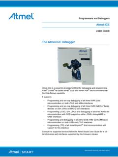
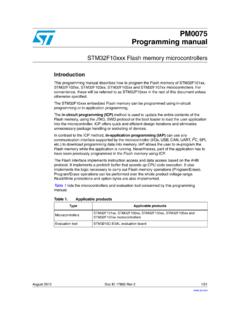
2 It is part of the ARM Debug interface Specification v5 and is an alternative to jtag . The physical layer of SWD. consists of two lines: SWDIO: a bidirectional data line SWCLK: a clock driven by the host Connecting to these pins allow an external device (such as a debug probe) to communicate directly with the Serial Wire Debug Port (SW-DP). The SW-DP in turn can access one or several Access Ports (APs). that give access to the rest of the system. The important AP on the EFM32 is the AHB-AP which is a bus 1. master on the Internal AHB bus of the Cortex-M3. In other words the AHB-AP can access the Internal memory map of the core. Since the Internal Flash , SRAM, debug components and peripherals all are memory mapped, this AP can control the entire device including Programming it.
3 Figure Serial Wire Debug interface AHB- AP. Cortex Mem ory SWDIO Map SW- DP. SWCLK Other AP. Other AP. Debug Pins The EFM32 has three pins used for debugging. Two of them are the SWDIO and SWCLK pins used by SWD. The last pin is called Serial Wire Output (SWO) and is used for debugging output. SWO is an asynchronous, one-directional protocol used by the Internal debug components in the core to output various debug information. This pin is not required to program the device. Out of reset both SWDIO and SWCLK are connected to SW-DP and configured with a weak Internal pull- up and pull-down, respectively. It is possible to disable both debug pins by configuring the GPIO_ROUTE.
4 Register. This can free up the pins to use them as GPIO. The SWO pin is initially disabled. Note Keep in mind that if the debug pins are disabled, a debugger will no longer be able to connect to the EFM32. During development, it is therefore a good idea to make sure there is a delay between reset and disabling the pins (typically a few seconds). In that way the debugger has time to connect and halt the CPU before the pins are disabled. If you have disabled the debug pins and are unable to connect to your device, see Section (p. 13) for instructions on how to perform the debug unlock sequence. When designing the debug header for a product it is common to also include the RESET pin and one pin for sensing the supply voltage in addition to ground.
5 1. AHB (Advanced High-performance Bus) is the Internal bus of the Cortex core 2013-11-26 - 2 ..the world's most energy friendly microcontrollers 2 Serial Wire Programmers Model This chapter describes the SWD protocol and how to communicate with the SW-DP and AHB-AP. The SWD Protocol In SWD terminology the host refers to the system controlling the debugger, the PC / debug probe. The target is the system which is under debug, the EFM32. SWCLK is a clock signal which is always driven by the host. Both sides will drive the SWDIO line to send data. A high value on SWDIO indicates a logical '1', a low value is a logical '0'. The protocol specifies when each side will drive the SWDIO line.
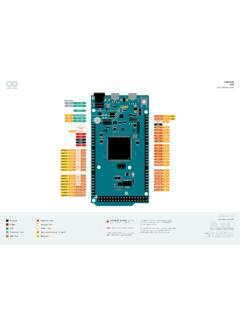
6 Three different phases are specified. Each transaction begins with the host sending a request. The target answers with an acknowledge which is followed by a data phase. Who controls the line during the data phase depends on the type of request issued by the host. If the host issued a write request, the host will drive the line. On a read request the target will drive the line to transmit data from the target to the host. In all phases data is transmitted LSB (least significant bit) first. The target will both sample and put data on the line on a rising clock edge. Figure SWD request it 2. it 3. it e sb sb r / w it P. it bit bit yb es es tb / D. ad dr dr p rit rk r St a St o AP.
7 Ad Ad Re Pa Pa 1 AP R A2 A3 P 0 1. The request phase consists of 8 bits. The meaning of each bit in the request is illustrated in Figure (p. 3) . The start bit is always 1. The next bit specifies whether the transaction is a DP (Debug Port) or AP (Access Port) transaction. If this bit is zero, the transaction is a DP access. Bit 2 is the read/write bit. If this bit is 1 the transaction is a read access (from target to host). Bit 3 and 4 are address bits A2 and A3. These bits specifies which out of four registers are selected for the transaction. Register selection is described in Section (p. 5) . Bit 5 is a parity bit. The parity bit is used by the target to verify the integrity of the request.
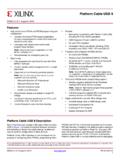
8 This bit should be 1 if bits 1-4 contains an odd number of 1's. If the number of 1's are even, the parity bit should be zero. Bit 6 is the stop bit. This bit is always zero. Bit 7 is the park bit. This bit is always one. The ack phase consist of three bits. An OK response has the value 1. Since values are put on the line LSB first an OK response looks like a 1 followed by two 0's on the line. Once the host has received an OK response the data phase can begin. The data phase consists of 32. data bits (one word) followed by 1 parity bit. The parity bit is calculated based on all the 32 data bits. If the number of 1's in the data word is odd, the parity bit should be 1.
9 The host must continue to clock the interface for at least 8 cycles after the data phase to make sure the transaction is clocked through the SW-DP. This can be done either by: starting a new transaction inserting idle clock cycles During idle clock cycles the SWDIO is driven low by the host. 2013-11-26 - 3 ..the world's most energy friendly microcontrollers Figure Successful Write Command (from [adi5]). Turnaround Periods Every time the SWDIO changes data direction, a one-cycle turnaround period is inserted which both sides should ignore. This means there is always a turnaround period between the request and acknowledge. On a write request, there is a turnaround period between acknowledge and the data phase.
10 On a read request there is a a turnaround after the data phase. Initialization Before using the SW-DP an initialization sequence must be performed to establish communication and bring the SW-DP to a known state. 1. Perform a line resest 2. Send the jtag -to-SWD switching sequence 3. Perform a line reset 4. Read the IDCODE register A line reset is performed by clocking at least 50 cycles with the SWDIO line kept HIGH by the host. The reason for the jtag -to-SWD sequence is that the Debug Port implementation is actually a SWJ-DP. SWJ-DP is a wrapper around both SW-DP and jtag -DP, the jtag counterpart to SWD. The EFM32. does not include jtag , but the switching sequence must still be performed as the default state required by the SWJ-DP specification is jtag .