Transcription of IEEE P1687 Internal JTAG (IJTAG) Tutorial
1 ieee P1687 Internal jtag ( ijtag ) Tutorial 2011 ASSET InterTech, Inc. ASSET and ScanWorks are registered trademarks while the ASSET logo is a trademark of ASSET InterTech, Inc. All other trade and service marks are the properties of their respective owners. ijtag Tutorial 2 Table of Contents Overview .. 2 Industry Drivers .. 3 The Synergy of Standards .. 4 Who will use ieee P1687 ijtag ? .. 4 The Basic P1687 On-Chip Architecture .. 5 The Instrument Gateway (Interface) .. 6 Managing 1687 scan paths with the Segment Insertion Bit (SIB) .. 7 ijtag Description Languages .. 7 The ijtag Network Building Block .. 8 Conclusion .. 9 Table of Figures Figure 1: The Basic ieee P1687 ijtag Architecture .. 5 Figure 2: The Instrument Gateway Interface .. 6 Figure 3: The Gateway Segment-Insertion-Bit (SIB).
2 7 Figure 4: The simplest ieee P1687 ijtag Network .. 8 ijtag Tutorial 3 Overview The goal of ieee P1687 Internal jtag ( ijtag ) is to streamline the use of instruments that have been embedded in chips. The intent is to facilitate the deployment of these embedded instruments in a wider array of chip, board and system level validation, test and debug applications. Over the last decade, semiconductor manufacturers have embedded instruments in their chips to simplify the characterization, testing and debugging of these devices. Given the right standards-based tools environment, these same instruments can perform a much broader spectrum of chip, board and system level validation, test and debug applications. Industry Drivers Several conditions in the electronics industry are motivating this trend toward embedded instrumentation and thereby have created a need for the ieee P1687 ijtag standard.
3 For circuit boards, the progress of advanced technologies such as complex microprocessors and very high-speed buses has outstripped the capabilities of the older legacy validation and test equipment. By and large, this legacy equipment is intrusive in that it is external to the board being tested and it relies upon placing a physical probe on some sort of an access point on the board or on a chip on the board. For a number of reasons, the effective availability of these access points is rapidly diminishing and this is reducing the validation and test coverage that can be achieved with legacy intrusive testers, such as oscilloscopes and logic analyzers for validation, and in-circuit test (ICT) and manufacturing defect analyzers (MDA) for production test. Because the testing of boards with external, intrusive instrumentation has become increasingly less effective, the industry has turned to non-intrusive software-based embedded instrumentation which executes out of hardware on the board being test and is not limited by physical probes.
4 At the chip level, there are several other factors that are driving the industry toward embedded instrumentation. Keeping pace with Moore s Law has meant that chips have become much denser in terms of the number of transistors per square millimeter. In addition, chip frequencies have gone up significantly and devices are much more complex. All of this means that characterization times are longer and more sophisticated test equipment is needed. Advanced chip packaging concepts such as stacking multiple die in three-dimensional packages also complicates chip-level characterization and debug. The time-to-market for electronic products is rapidly shrinking and this affects all aspects of a product s development cycle, including validation and test. For example, the average life of a cell phone today is approximately eight months.
5 In the past, test routines were developed separately for each phase of product development and manufacturing. Now, the industry cannot afford the luxury of the extra time that is needed to re-develop tests for a product as it transitions from each phase in its life. Portable tests and other routines that accompany chips and which can be re-applied in every phase of a product s life cycle are becoming a necessity because of the shorter life cycles. To achieve this level of portability the tests must capitalize on embedded instrumentation. One way to do so will be the capabilities of the ieee P1687 ijtag standard. ijtag Tutorial 4 The Synergy of Standards To fully capitalize on embedded instrumentation, several other standards besides the ieee P1687 ijtag standard often work together. These would include the ieee Boundary-Scan Standard and its enhanced version, the ieee Enhanced Boundary-Scan Standard, as well as the ieee 1500 Core Test Standard.
6 Who will use ieee P1687 ijtag ? The ieee P1687 ijtag standard will be applied at the chip and board levels. Chip designers, for example, will find ijtag useful during design verification when it will be used in conjunction with a simulator or emulator. ijtag will also be deployed in the ATE test environment where it will become part of chip test, chip debug/diagnostics and chip characterization. At the circuit board level, the ieee P1687 ijtag standard will be used to access instruments that are embedded in chips to perform board-level test, debug/diagnostics and characterization. Finally, when a system is failing in the field, maintenance personnel can utilize the same tests based on embedded instruments to extract failure data from a device. This data, along with other environmental data, such as voltage and temperature, can be fed back to the organization s failure analysis team which can analyze the root causes of failures.
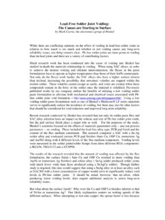
7 This will allow the duplication of the failure conditions and as a consequence reducing reduction in the amount of No Trouble Found (NTF) cases. ijtag Tutorial 5 The Basic P1687 On-Chip Architecture Figure 1: The Basic ieee P1687 ijtag Architecture 2# 17 ASSET 2011 The Graphic View of the P1687 ArchitectureSiBTDRRWMBISTDoneFailResetRu nTDRRWMBISTDoneFailResetRunSiBSiB The Controller TAP &TAP Controller BSDL The Instrument IP, Design-ware, EDA Gen Portable/Reusable Raw Instrument ICL, PDL The P1687 Scan-Path Network Design-ware, EDA Generated Compliant to P1687 Rules P1687 Network ICLPDL Vectors go hereTCKTMSTDITDOTAPC ontrollerPDL Vectors go hereIR=10111 Not P1687 Not P1687 Yes, P1687 Tutorial : ijtag Basics The figure above illustrates the architecture that the ieee P1687 ijtag standard would implement at the chip level.
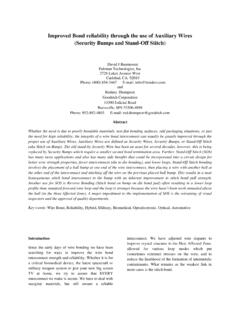
8 On the right, it shows how the ijtag network interfaces to the ijtag -compliant embedded instruments with the ieee boundary-scan standard s Test Access Port (TAP) on the left. The TAP functions as the interface for the embedded P1687 ijtag architecture to the world outside of the chip. Essentially, ieee P1687 ijtag allows the boundary-scan TAP and its TAP Controller to access instruments that are embedded on-chip. Several ijtag concepts are shown in this illustration, including the Segment Insertion Bit (SIB) and Procedural Description Language (PDL). These will be described at greater length below. ijtag Tutorial 6 The Instrument Gateway (Interface) Figure 2: The Instrument Gateway Interface 2# 16 ASSET 20111687 Hardware Interfaces: 1687 Starts at GWTDITDOABCDEFGHTDITDOL evel-0 Gateway isbeginning of 1687 Update-EnfromSerialOutShift-EnCapture-En ResetNTCKS electtoSerialInEmbedded IPwithEmbeddedInstrumentsand its ownGatewayEmbedded IPwith its ownEmbeddedInstruments, Gateway, and doubly embedded IPDoublyEmbedded IPwithEmbeddedInstrumentsand its ownGatewayLevel-0 Gateway for IPbecomes Level-1 Gatewaywhen integratedLevel-0 Gateway for IP becomes Level-1 Gateway tocompound IP and Level-2 Gateway when integrated into chipScalabilityandIP ReusabilityTDR Interface Port FunctionsVectors are deliveredwith the Instrumentand tools retargetthem = portable reuseThe 1687 Standard starts at the Gateway, not the TAP, to allow portable IP and other future controllersTutorial.
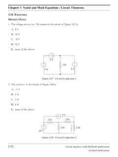
9 ijtag Basics The above drawing illustrates how the hardware interface or gateway for the ieee P1687 ijtag standard on-chip architecture can interface to a standard ieee boundary-scan standard Test Data Register (TDR). Isolating the P1687 ijtag architecture from the requirements of the interface leading off the chip ensures the portability of embedded instrument intellectual property (IP) as well as any vector IP that may be associated with them. In fact, an off-chip interface other than the ieee boundary-scan TDR could emerge in the future and this would not affect the portability of ieee P1687 ijtag instruments or vectors. ijtag Tutorial 7 Managing 1687 scan paths with the Segment Insertion Bit (SIB) Figure 3: The Gateway Segment-Insertion-Bit (SIB) 2# 12 ASSET 2011 The Gateway Segment-Insertion-Bit (SIB)The Key Element for Adding, Organizing, Managing Embedded ContentTDIS hift-Update Cellused as a SIBS electTCKUTDO fromScanOuttoScanInSCThe HIPScan Path Management BitThe Gateway Register is made of one or more of these SIBsViolates Tenet of Separation of Instruction & Data Tutorial : ijtag Basics One of the key elements defined in the ieee P1687 ijtag standard is the Segment Insertion Bit (SIB).
10 The composition of a SIB is shown in the illustration above. A SIB is similar to an ieee boundary-scan shift/update cell, but the SIB is used to dynamically configure an on-chip P1687 ijtag scan path to meet the requirements of a particular set of test vectors. Selecting a certain SIB can activate a portion of the chip s ijtag scan path and consequently activate the instrument(s) on that segment of the scan path. Conversely, de-selecting a SIB will deactivate a portion of the chip s overall scan path and render the instruments on that segment inaccessible. Instruments on a deactivated segment of the scan path cannot be accessed as long as the scan path segment is deactivated, but they can still execute test vectors while they are offline. ijtag Description Languages There are two description languages defined by the ieee P1687 ijtag standard: Instrument Connectivity Language (ICL) and Procedural Description Language (PDL).