Transcription of LEAD FREE Series LF909 - Watts
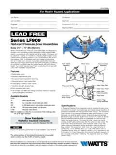
1 Series LF909 Reduced Pressure Zone AssembliesLF909 Sizes: 3 4", 1" (20, 25mm) LF909M1 Sizes: 11 4", 11 2", 2" (32, 40, 50mm) Series LF909 Reduced Pressure Zone Assemblies are designed to provide superior cross-con nec tion con trol pro tec tion of the potable water sup ply in accordance with na tion al plumb ing codes and con tain ment control for water au thor i ty re quire ments. This Series can be utilized in a va ri ety of in stal la tions, in clud ing health hazard cross-con nec tions in plumb ing sys tems or for con tain ment at the service line entrance. The LF909 features Lead Free* con-struction to comply with Lead Free* installation requirements. With its ex clu sive, design in cor po rat ing the air-in/wa ter-out" prin ci ple it pro vides maximum relief valve dis charge during the emer gen cy con di tions of com bined backsi pho n age and backpres sure with both checks fouled.
2 Model LF909QT, standardly furnished with full port, resilient seated and Lead Free* cast copper silicon alloy ball valve shutoffs. Siz es 3 4" and 1" (20 and 25mm) shutoffs have tee Modular design Replaceable seats Compact for installation ease Horizontal or vertical (up or down) installation on limited sizes only No special tools required for servicingSpecificationsA Reduced Pressure Zone Assembly shall be in stalled at each cross-connection to prevent back si pho n age and backpres sure of haz ard ous ma te ri als into the potable water sup ply. The as sem bly shall consist of a pres sure dif fer en tial relief valve located in a zone between two pos i tive seating check valves. Back si pho n age pro-tec tion shall include provision to ad mit air directly into the reduced pres sure zone via a separate channel from the water discharge chan nel, or directly into the supply pipe via a separate vent.
3 The assembly shall be constructed using Lead Free* cast copper sili-con materials. The Lead Free* reduced pressure zone assembly shall comply with state codes and standards, where applicable, requiring reduced lead content. The assembly shall include two tightly clos ing shutoff valves before and after the as sem bly, test cocks and a pro tec tive strain er upstream of the No. 1 shutoff valve. The as sem bly (spec i fy Model LF909 for tem per a tures up to 140 F (60 C) or Mod el LF909HW for temperatures up to 210 F (99 C)) shall meet the re quire ments of ASSE Std. 1013; AWWA Std. C-511-92 CSA ; FCCCHR of USC Manual Section 10. Listed by IAPMO (UPC). SBCCI (Standard Plumbing code). The assembly shall be a Watts LF909 QTS or LF909M1QT-S 11 2" (40mm)Ball Valve Test CocksFirst CheckModuleAssemblySecond PressureChannel toRelief ValveRelief ValveAssemblyWater OutletAir InletLEAD FREE*Job Name Contractor Job Location Approval Engineer Contractor s No.
4 Approval Representative ES- LF909 SFor Health Hazard Applications*The wetted surface of this product contacted by consumable water contains less than of lead by AvailableWattsBox Insulated more information, send for literature product specifications in customary units and metric are approximate and are provided for reference only. For precise measurements, please contact Watts Technical Service. Watts reserves the right to change or modify product design, construction, specifications, or materials with-out prior notice and without incurring any obligation to make such changes and modifications on Watts products previously or subsequently information contained herein is not intended to replace the full product installation and safety information available or the experience of a trained product installer.
5 You are required to thoroughly read all installation instructions and product safety information before beginning the installation of this Quarter-turn ball valves S Bronze strainerHW Stainless steel check modules for hot and harsh water conditions The installation of a drain line is recommended. When in stall ing a drain line, an air gap is necessary. MaterialsBody: Lead Free* Cast Copper Silicon AlloyCheck Seats: 909 Celcon Relief Valve Seats: Stainless Steel 909HW Test Cocks: Lead Free* Cast Copper Silicon Alloy Celcon is a registered trademark of Celanese, LimitedConnections3 4" 1" (19 25mm) 909-NPT Female threaded body connection11 4" 2" (32 50mm) 909-M1-NPT Male threaded body con nec tionStandardsAWWA C-511-92 FCCCHR of USC Manual Section 10 IAPMO (UPC), SBCCI (Standard Plumbing code)Tested and Certified by NSF International ApprovalsListed by IAPMO Listed by SBCCI Approved by the Foundation for Cross-Connection Control and Hydraulic Research at the University of Southern Cal i for nia.
6 (QT and S Models)Vertical flow-up" approval only on 3 4" (20mm) and 1" (25mm) sizes (model LF909QT).Pressure TemperatureTemperature Range: 33 F 140 F ( C 60 C) continuos, 180 F (82 C) intermittentMaximum Working Pressure: 175psi ( bar) Series LF909HW:Temperature Range: 33 F 210 F ( C 99 C)Maximum Working Pressure: 175psi ( bar) LASBESCDM odel LF909QT-SPModel LF909 QTELAD imensions WeightsWhen installing a drain line use 909AG Series Air Gaps on Series 909 back flow preventers. 909EL se ries elbows are for air gaps on back flow pre ven ters in vertical in stal la it OperatesThe unique relief valve con struc tion in cor po rates two channels: one for air, one for water. When the relief valve opens, as in the ac com pa-ny ing air-in/water-out di a gram, the right-hand chan nel admits air to the top of the re duced pressure zone, re liev ing the zone vacuum.
7 The chan-nel on the left then drains the zone to at mo sphere. Therefore, if both check valves foul, and si mul ta neous nega-tive supply and pos i tive backpressure develop, the re lief valve uses the air-in/water-out prin ci ple to stop potential back OUTAIR INSeries 909AG Air Gaps 909 DRAIN OUTLET DIMENSIONS WEIGHTS Iron Body Sizes Sizes A B No. Desc. in. mm in. mm in. mm in. mm lbs. kg. 909AG-C Air Gap 3 4,1 19,25 1 25 31 4 83 47 8 124 11 2 .7 909EL-C Elbow 3 4,1 19,25 23 8 60 23 8 60 3 8 .2 909AG-F Air Gap 11 4-2 32-50 2 50 43 8 111 63 4 171 31 4 909EL-F Elbow 11 4-2 32-50 35 8 92 35 8 92 2 . toNSF/ANSI 61-G & 372* SIZE (DN) DIMENSIONS WEIGHT A As B C D E Es L P QT QT-S in.
8 Mm in. mm in. mm in. mm in. mm in. mm in. mm in. mm in. mm lbs. kgs. lbs. kgs. 3 4" 143 8 365 181 16 459 83 4 222 4 102 43 4 121 63 4 171 103 16 259 75 16 186 37 8 98 14 1" 153 8 391 195 8 498 83 4 222 4 102 43 4 121 7 178 11 279 75 16 186 37 8 98 15 11 4"M1 181 2 470 237 16 595 115 8 295 51 2 140 61 2 165 71 2 191 123 16 310 103 8 264 51 4 133 40 11 2"M1 19 483 243 8 619 115 8 295 51 2 140 61 2 165 71 2 191 125 8 321 103 8 264 51 4 133 40 2"M1 191 2 495 2515 16 659 115 8 295 51 2 140 61
9 2 165 73 4 197 1315 16 354 103 8 264 51 4 133 40 S = strainer modelCapacityAs compiled from documented Foundation for Cross-Connection Control and Hydraulic Research of the University of Southern California lab tests. Typical maximum system flow rate ( feet/sec.) kPa psi 110 16 83 12 55 8 28 40 5 10 15 20 25 30 35 gpm 0 19 38 57 76 95 114 133 lpm 5 10 15 20 fps mps *0 5 10 15 20 25 30 35 40 45 50 55 60 gpm 0 19 38 57 76 95 114 133 152 171 190 209 228 lpm 5 10 15 20 fps mps *0 10 20 30 40
10 50 60 70 80 90 100 gpm 0 38 76 114 152 190 228 266 304 342 380 lpm 5 10 15 20 fps mps *0 10 20 30 40 50 60 70 80 90 100 gpm 0 38 76 114 152 190 228 266 304 342 380 lpm 5 10 15 fps mps 3 4" (20mm) 1" (25mm) 11 4" (32mm) 11 2" (40mm) kPa psi 138 20 103 15 69 10 35 5 kPa psi 138 20 103 15 69 10 35 5 kPa psi 138 20 103 15 69 10 35 5*0 25 50 75 100 125 150 175 200 gpm 95 190 285 380 475 570 665 760 lpm 5 10 15 fps mps 2" (50mm) kPa psi 138 20 103 15 69 10 35 5LF909QT, LF909QT-S ES-LF909S 1750 2017 WattsUSA: T: (978) 689-6066 F: (978) 975-8350 : T: (905) 332-4090 F: (905) 332-7068 America: T: (52) 81-1001-8600