Transcription of LEAD FREE Series LF909 - Watts
1 For Health Hazard ApplicationsES- LF909 LJob Name Contractor Job Location Approval Engineer Contractor s No. Approval Representative LF909 Series LF909 reduced pressure Zone AssembliesSizes: 21 2" 10" (65 250mm) Series LF909 reduced pressure Zone Assemblies are designed to provide cross-connection control protection of the potable water supply in accordance with national plumbing codes.
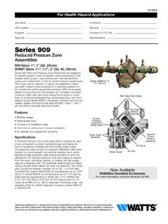
2 This Series can be utilized in a variety of installations, including health hazard cross-connections in plumbing systems or for containment at the service line entrance. With its exclusive relief valve design incorporating the air-in/water-out" principle, it provides substantially improved relief valve discharge performance during the emergency conditions of combined backsiphonage and backpressure with both checks fouled. The LF909 features Lead Free* construction to comply with Lead Free* installation Replaceable seats Stainless steel internal parts No special tools required for servicing Captured spring check assemblies Fused epoxy coated & lined checks Industrial strength sensing hose Field reversible relief valve Air-in/water-out relief valve design provides maximum capacity during emergency conditionsAvailable ModelsSuffix.
3 LF without shutoff valvesNRS non-rising stem resilient seated gate valvesOSY - UL/FM outside stem & yoke resilient seated gate valvesQT-FDA FDA epoxy coated quarter-turn ball valvesS-FDA FDA epoxy coated strainer Note: The installation of a drain line is recommended. When installing a drain line, an air gap is ValveFirst CheckAssemblySecond CheckAssemblyRelief Valve SeatRelief Valve PistonRelief ValvePiston AssemblyWiper SealBottom PlugSpring AssemblyPipe Line CenterRelief ValveBody FlangeNow AvailableWattsBox Insulated more information, send for literature FREE*SpecificationsA reduced pressure Zone Assembly shall be installed at each cross-connection to prevent backsiphonage and backpressure backflow of hazardous materials into the potable water supply.
4 The assembly shall consist of a pressure differential relief valve located in a zone between two positive seating check valves and captured springs. Backsiphonage protection shall include provision to admit air directly into the reduced pressure zone via a separate channel from the water discharge channel. The assembly shall include two tightly closing shutoff valves before and after the valve and test cocks. The Lead Free* reduced pressure Zone Assembly shall comply with state codes and standards, where applicable, requiring reduced lead content.
5 The assembly shall meet the requirements of ASSE Std. 1013; AWWA Std. C511-92; CSA ; and UL Classified File No. EX3185. Listed by IAPMO (UPC). Approved by the Foundation for Cross-Connection Control and Hydraulic Research at the University of Southern California. The assembly shall be a Watts Series LF909 .* The wetted surface of this product contacted by consumable water contains less than of lead by product specifications in customary units and metric are approximate and are provided for reference only. For precise measurements, please contact Watts Technical Service.
6 Watts reserves the right to change or modify product design, construction, specifications, or materials with-out prior notice and without incurring any obligation to make such changes and modifications on Watts products previously or subsequently with governing authorities for local installation requirements2 MaterialsCheck Valve Bodies: FDA epoxy coated cast ironSeats: Stainless steelTrim: Stainless steelRelief Valve Body: 21 2"-3" (60-80mm) Lead Free* cast copper silicon alloy 4"-10" (100-250mm) FDA epoxy coated cast ironTest Cocks: Lead Free* copper silicon alloyPressure TemperatureTemperature Range: 33 F-110 F ( C-43 C) continuous, 140 F (60 C) intermittentMaximum Working pressure : 175psi ( bar)StandardsAWWA C511-92 IAPMO PS 31, SBCCI (Standard Plumbing Code)USC manual for Cross-Connection Control, 8th EditionCapacity*Typical maximum flow rate ( feet/sec.)
7 21 2" (65mm) ** P 0 25 50 75 100 125 150 175 200 225 250 275 300 gpm 0 95 190 285 380 475 570 665 760 855 950 1045 1140 lpm 5 15 fps
8 Mps kPa psi 138 20 103 15 69 10 35 53" (80mm) * P 0 50 100 150 200 250 300 350 400 gpm 0 190 380 570 760 950 1140 1330 1520 lpm 5 15 fps mps kPa psi 138 20 103 15 69 10 35 54" (100mm) * P 0 100 200 300 400 500 600 gpm 0 380 760 1140 1520 1900 2280 lpm 5 10 15 fps mps kPa psi 138 20 103 15 69 10 35 56" (150mm)
9 * P 0 200 400 600 800 1000 1200 1400 1600 gpm 0 760 1520 2280 3040 3800 4560 5320 6080 lpm 5 15 fps mps kPa psi 138 20 103 15 69 10 35 58" (200mm) * P 0 200 400 600 800 1000 1200 1400 1600 1800 2000 gpm 0 760 1520 2280 3040 3800 4560 5320 6080 6840 7600 lpm 5 10 fps mps kPa psi 138 20 103 15 69 10 35 510" (250mm)
10 * P 0 500 1000 1500 2000 2500 3000 gpm 0 1900 3800 5700 7600 9500 11400 lpm 5 10 fps mps kPa psi 138 20 103 15 69 10 35 5 How It OperatesThe unique relief valve construction incorporates two channels: one for air, one for water.