Transcription of Lead Free Solder Reflow - IXYS Corporation
1 1 IXYS Corporation - Bassett Street; Santa Clara, CA 95054; Tel: (408) 982-0700; Fax: (408) 496-0670 2006 IXYS All rights reservedAN 0601 Lead Free Solder Reflow for Semiconductor Power DevicesThe solders used in the Electronic Industry arerapidly converting from Tin/Lead (Sn/Pb) solders toLead-Free (Pb-Free) solders to meet newenvironmental and Green requirements. Many ofthese requirements are controlled by laws andregulations, which vary by country and has been a parallel shift for years from through-hole to surface mount assembly, which can oftencompound the Pb Free soldering issues. This paperwill address the optimization of Pb Free solderingconditions, with a focus on differences between Sn/Pb and Pb Free soldering.
2 This allows assemblers tobuild on their extensive experience with Melting Point of Pb-Free SoldersPb Free solders are usually Tin/Silver (Sn/Ag) Solder , or variations on Sn/Ag solders. The primarydifference affecting the soldering process is that theSn/Ag Solder has a higher melting point than the Sn/Pb Solder . The melting point of the Sn/Ag eutectic( ) is 37C higher than the Sn/Pbeutectic (63Sn/37Pb). The nominal eutectic meltingpoints are 220 C for Sn/Ag Solder and 183 C forSn/Pb off eutectic Pb-Free solders have even highermelting points. The 95Sn/5Ag Solder melts at 240 C,and there are Sn/Ag/Cu and other alloys that spanthe melting point range from 220 to 240 C. Evenwhen Sn/Ag eutectics solders are used, dissolvedplating materials like Ag, Sn and Au can oftenincrease the melting point to 240 C.
3 Furthermore,the melted Solder can exist in multiple phases, oneof which does not melt until 240 C, which reducesthe flow and wettability of the Sn/Ag solders below240 C. As a result of these issues, it is generallywise to assume the worst case melting point of allthe Sn/Ag Pb-Free solders as 240 C. This can makethe effective melting point of the Pb-Free solders47C higher than the Sn/Pb Reflow Temperatures of Pb-Free SoldersThe higher melting points of the typical Pb-Free(Sn/Ag) solders requires Reflow to occur above240 C. The recommended soldering or Reflow profilemust assure a minimum time above 240 C that takesinto account equipment temperature tolerances, andwith varying product and component size and semiconductor components can include largerand more massive components as well as the standardsmaller components.
4 This makes it more difficult tooptimize the Reflow process for all components onthe PCB industry has extensive experiencereflowing components with Sn/Pb solders, whichtypically have peak Reflow temperature of 215-245 Cwith 20-60 seconds above 183 C. If we were to add47C to these temperatures for ideal Reflow andwetting, the temperatures would be so high that theycould damage components, burn and harden fluxes,and oxidize some solderable surfaces. Thesemaximum Reflow temperature limits combined withthe higher Pb-Free melting points define a narrowerand more critical Reflow temperature range for thePb-Free solders. The typical Reflow temperature rangefor Pb-Free (Sn/Ag) Solder is 240-250 C with 40-80seconds over 220 should be noted that the recommended Sn/Pbreflow temperature range is less critical, and thatminor deviations in temperature of equipment andcomponents generally do not create solderingproblems.
5 In contrast, the Pb-Free Solder reflowtemperatures can be more sensitive to low or hightemperatures, and can result in serious problems asdescribed above. Therefore, Reflow temperature limitsshould be set and monitored more precisely for Pb-Free soldering. The actual temperature of small orlarge components should be checked during reflowprofile setup. It is also important to check thecomponents maximum temperature ratings whenusing Pb-Free soldering, and this is especially2 IXYS Corporation - 3540 Bassett Street; Santa Clara, CA 95054; Tel: (408) 982-0700; Fax: (408) 496-0670 2006 IXYS All rights reservedAN 0601important with surface mount components, where theentire component generally reaches the peak reflowtemperature.
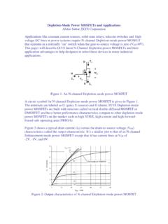
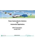
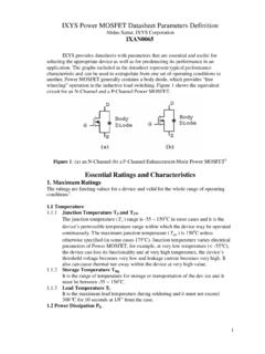
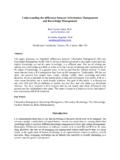
6 Although most semiconductorcomponents today are suitable for both surface mountand Pb-Free solders, there are exceptions and themaximum soldering temperatures or suitableassembly processes should be confirmed. The solderprofile can also be influenced by high componentdensity, heavy copper foil, and other page 3, Figure 1 show a typical Solder reflowprofile for a Pb-Free (Sn/Ag) Solder and Figure 2shows a typical Solder Reflow profile for Sn/Pbeutectic Pre-Heat and Heating Rate for Pb-FreeSoldersThe preheat cycle and maximum heating ratesfor Sn/Pb and Pb-Free solders are not significantlydifferent, and are generally not dependent on the typeof Solder preheat time and temperature are determinedprimarily by the flux system.
7 The flux must cleanand remove oxidation for the surfaces to be soldered,which includes PCB and component leads. Solderpastes often include both flux and volatile organicfiller materials. The preheating removes excessvolatile materials, while the fluxes are doing typical preheat conditions are 80 to 120seconds between 150 C and 200 C, but since thepreheat cycle is dependent on the flux system, thepreheat cycle recommended by the flux or solderpaste manufacturer is best. In general, the same fluxsystems are used for Sn/Pb and Pb-Free maximum heating rate is typically limitedto /second, but most Reflow systems heatconsiderably slower because of the mass and Cooling RateThe maximum cooling rate is typically /second, and is limited to prevent damage to solderjoints or components cause by mechanical stressesgenerated by CTE, (Coefficient of ThermalExpansion), mismatches between the componentsand the general, it is advantageous to cool near themaximum rate.
8 The maximum cooling rate keeps thesolder from devitrifying (crystallizing), whichimproves the mechanical properties of the Solder . Thesolder finish should be shiny after cooling; a dullfinish being evidence of rates can be more critical with Pb-Freesolder Reflow , because the temperature differentialbetween solidification and room temperature is muchgreater than with Sn/Pb solders. The temperaturedifferential for Pb-Free solders is 215 C (240-25)and for Sn/Ag Solder is 158 C (183-25). A gradualcooling rate allows these soft solders to creep , andrelease the mechanical stresses, (which areproportional to the product of the CTE, temperaturedifferential and total component length). Therefore,larger components, and components with CTEssignificantly different than the PCB CTE are moresusceptible to CTE mismatch cooling SummaryThe soldering of semiconductor devices to PCBhas historically used Sn/Pb solders, but Pb-Freesolders are increasingly being used to eliminate Pbas required by environmental regulations.
9 Most PbFree solders suitable for these applications are Sn/Ag alloys with higher melting points, withcorrespondingly higher Solder Reflow higher Reflow temperatures are limited bythe maximum allowable temperatures of componentsand fluxes. This creates a narrow Reflow temperaturewindow for Pb-Free Solder Reflow . The optimizationof the Pb-Free Solder Reflow profiles is therefore morecritical than Sn/Pb Solder Reflow profiles. Pb Freesoldering can also be more critical for powercomponents and other larger mass components,which take longer to Pb-Free solders use the same flux systemsas Sn/Pb solders, and therefore use similar preheatand heating rate Corporation - Bassett Street; Santa Clara, CA 95054; Tel: (408) 982-0700; Fax: (408) 496-0670 2006 IXYS All rights reservedAN 0601Pb-Free Solder maximum cooling rates are ideallythe same as Sn/Pb solders, but sometimes can beproblematic because they cool from a highertemperature.
10 Large components and components withextreme CTE are the most solders are more environmentallyfriendly, and are suitable for soldering mostsemiconductor components with appropriate reflowprofile changes and - Seconds04080120160200240280320360 Temperature - OC0255075100125150175200225250275300 TypicalMaximumMinimumFigure 1. Typcial Solder Reflow Profile for a Lead-Free (Sn/Ag) SolderTime - Seconds050100150200250300350 Temperature - OC0255075100125150175200225250275 TypicalMaximumMinimumFigure 2. Typcial Solder Reflow Profile for a Lead-Tin (Pb/Sn) Solder