Transcription of LEAD/LAG CONTROLLERS MODEL PSP & BSP
1 LEAD/LAG CONTROLLERS MODEL PSP & BSPGENERAL DESCRIPTION:Toxalert has two basic LEAD/LAG controller types. One designed for dual circulating pumps and theother to automatically sequence boilers when they are to be controlled in a lead/standby AUTO:Both controller types feature an internal ON-OFF-AUTO switch mounted on the printed circuit boardthat operates the controlled equipment. In the AUTO position the controller automatically operatesthe controlled equipment via a SPST outdoor air thermostat. In the ON position the equipment ispositively turned ON, and positively turned off in the OFF position. The ON-OFF-AUTO switchfunction can be remotely controlled by installing a three position switch remote from the Lead/Lagcontroller (See technical description). LEAD/LAG :The LEAD/LAG switch is also mounted on the printed circuit board and is designed to choose the leadequipment.
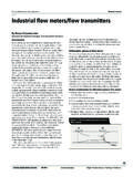
2 With the switch in the R-1 (relay #1) position, pump #1 or boiler #1 is in the LEAD position and equipment operated by relay 2 is automatically in the lag or standby position. With theswitch in the R-2 position the equipment (pump or boiler) operated by relay #2 is in the lead position,and equipment connected to R-1 automatically becomes the lag or standby equipment. TheLEAD/LAG switch function may also be controlled remotely by simply installing a remote SPST switch. (See technical description.)Pump/Boiler Sequencer Panels(CM) Custom Mount ModelsPSP-10CM shown TOXALERT TOXALERT INTERNATIONAL, Inc., PO Box 159, Mound, MN. 55364 PHONE: (952) 472-4541 FAX: (952) 472-4960 : LOW VOLTAGE CONTROL CIRCUITRYFlow Switch and outside air thermostat operation(24 VAC). LIGHT EMITTING DIODES (LED s) forstatus indication, long life, maintenance ) POWER ON (Green)2) FLOW NORMAL (Green)3) FAILURE (Red) SPDT CONTACTS FOR REMOTEALARM ANNUNCIATION ALL MODELS will operate on 120, 208 or 240 VAC ON-OFF-AUTO OPERATION:AUTO requires outdoor air thermostat to activatesequencer positive OFF of positive On of system, bypasses the outdoorair thermostat.
3 REMOTE CONTROL: LEAD/LAG switch and ON-OFF-AUTO switchfunctions can easily be operated remotely (lowvoltage. FIELD PROGRAMMABLE TIME DELAY:Delay of lag function operation. Pump controllertime delay from 10 seconds to 3 minutes. Boilercontroller 30 seconds to 16 MODELS:The PSP, Pump Sequence Panels are available in four models, MODEL PSP-10 & PSP-12 are electroniccontrollers housed in a 12 W x 14 H x 4 D surface mount enclosure with key locking hinged PSP-10 CM and PSP-12 CM are electronic CONTROLLERS mounted on a W 2 14 H steelmounting plate for incorporation into a custom control panel. The PSP models also come with twodifferent output relay contact ratings, PSP-10 and PSP-10CM models have contacts rated for 15 A. at120/220 VAC, and the PSP-12 and PSP-12 CM contacts are rated for 30A at 120/220 Numbers are:PSP-10 and PSP-10CM*PSP-12 and PSP-12CM*The BSP, Boiler Sequence Panels, CONTROLLERS are also available with and without surface mountenclosures.)
4 The MODEL BSP-15 controller is housed in a 12 W x 14 H x 4 D surface mountenclosure with key locking hinged door and BSP-15 CM controller is mounted on a W x 14 Hsteel mounting plate. Both models have an output relay contact rating of 15A at 120 Numbers are:BSP-15 and BSP-15CM**CM=Custom mount ( controller mounted on steel platefor incorporation into custom panel.)TIMING:All PSP-10 and 12 CONTROLLERS are shipped from the factory with a 30 seconds delay and all BSP-15controllers are shipped from the factory with a 6 minutes delay unless other time delay period isrequested. The time delay period starts when the outdoor air thermostat calls for pump/boiler to start,or if the On-Off-Auto switch is switched to On . If the pump/boiler does not proof operation withinthe time delay period then the standby pump/boiler is turned on by the INTERNATIONAL, Inc.
5 , PO Box 159, Mound, MN. 55364 PHONE: (952) 472-4541 FAX: (952) 472-4960 OF OPERATION (PUMP SEQUENCE):In circulating pump applications, two circulating pumps are ordinarily used in the water line, a lead or main operating pumpand a standby or backup pump. The Lead pump manual selector (S3) is placed in either the R-1 or R-2 position forselection of the lead pump. The green LED indicates a Flow-Normal condition whenever either pump P-1 or P-2 isoperating normally. If the lead pump fails to operate the SPDT pressure differential or flow switch (supplied by others)power the time delay circuit. If the flow is interrupted for more than 30 seconds (adjustable 10 seconds to 4 minutes), thetime delay relay will simultaneously deenergize the lead pump, energize the standby pump, activate the red LEAD PumpFailure LED and trigger the remote alarm circuitry.
6 A set of form C alarm contacts are brought out to the low voltageterminal strip for remote alarm indication. 24 VAC (30VA max.) can be picked up from the terminals H and N on TB-1and fed through the alarm contacts to power a remote alarm device(s).After an alarm indication and after the cause of the interruption has been eliminated, by repairing or replacing the lead pump,the square red Reset button (S2) on the board, must be depressed to reestablish the selected lead/standby sequence,turn off the red lead Pump Failure LED, and reset the remote alarm contacts. The continuous indication of the green Function Normal LED again indicates lead pump LEAD/LAG manual selector switch (S3) mounted on the board can be placed in either the R-1 or R-2 position. In case of lead pump failure , the sequence will always index to the standby pump; P-2 or P-1, no matter whichpump is selected as the lead pump.
7 In the event of power failure, the sequence will immediately start the lead pump whenpower is restored. If the lead pump has failed, the standby pump will begin operating after the 30 second flow OF OPERATION (BOILER SEQUENCE):The sequence of operation for the boiler controller is the same as for the pump controller except that the delay time is 6minutes (standard) rather than 30 seconds for the pump sequence. Also, the proof of operation device, pressure sensor,thermostat, or other proof of operation device (supplied by others) would be different from the pump flow proving :The Toxalert LEAD/LAG CONTROLLERS with cabinets may be mounted on the wall and is not position sensitive. The CM (customer mounted) CONTROLLERS can be mounted in any custom control panel and will require approximately W H x :The sequencer is provided with line voltage power supply connections and pump relay connections in the top of the low voltage, eight station terminal strip is located on the bottom of the board to connect the outdoor air thermostat, theSPDT flow (or operations) indication device and optional remote alarm Panel(s).
8 The Pump Sequence panels are assembledto permit low voltage wiring to enter through the bottom. If the LEAD/LAG and/or the ON-OFF-AUTO switches are to beremotely mounted they can be wired with wire as small as #18 and may be up to 200 feet from its controller . All wiring mustbe in accordance with applicable national and local electrical LEAD/LAG OPERATION:The LEAD/LAG function can easily be accomplished by mounting a SPST switch in a remote location. The wiring is 24 VACand will require a switch that can switch .5A. Wire the remote switch across terminals H and LL of TB2 mounted in theupper left corner of the printed circuit board. Cut jumper J-2 to disable the board mounted LEAD/LAG switch. When theremote LEAD/LAG switch is in the open position, Relay #1 will control the lead equipment. With the switch closed, relay #2will control the lead equipment and relay #1 will control its standby ON-OFF-AUTO:Remote ON-OFF-AUTO can easily be accomplished by mounting a DPDT switch with ON-OFF-AUTO action, in a remotelocation.
9 The wiring is 24 VAC and will require a switch than can switch .5A. Wire the remote ON-OFF-AUTO switch asdescribed. A spare terminal with the neutral (N) side of 24 VAC is furnished on TB1. Wire (N) terminal to common ofremote switch. The auto side of the remote switch is to be wired to terminal 1 of TB4, and the on side to terminal 2 of jumper J1 and J3 to deactivate the PC board AUTO-OFF-ON INTERNATIONAL, Inc., PO Box 159, Mound, MN. 55364 PHONE: (952) 472-4541 FAX: (952) 472-4960 #1 TABLE #2* TR resistors are mounted on the Timing Registor (TR) terminal strip (TB3) which is mounted on the board. or watt resistors may be used.** Time delay of standard AUXILIARY EQUIPMENT (Supplied by Others)A) SPDT Differential Pressure Switch or Flow SwitchSuggest: Robertshaw PF-126 Floating D Differential Pressure switch orPenn P74FA-5 pressure Differential ) Outside air thermostat for AUTOMATIC : Honeywell T675, or Columbus Electric LB100 (SPST) or LB200 (DPST) remote bulb thermostats, or TC-100series remote bulb CONTROLLERS from Dynacon.
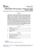
10 Toxalert has controlling devices you need for application. Please controller EXTERNAL WIRINGPSP-10 & PSP-12TR VALUES IN OHMS RESULTING TIME DELAY100K10 seconds300K 30 seconds **620K1 minute meg2 minutes meg3 minutes meg4 minutesBSP-15 & BSP-15 CMTR VALUES IN OHMS RESULTING TIME DELAY100K30 seconds200K1 minute360K2 minutes560K3 minutes750K4 minutes910K5 minutes meg 6 minutes ** meg 7 minutes meg minutes meg 10 minutes meg 11 minutes meg 16 minutes TOXALERT INTERNATIONAL, Inc., PO Box 159, Mound, MN. 55364 PHONE: (952) 472-4541 FAX: (952) 472-4960