Transcription of Learning ObjecTive Key Terms - Pearson
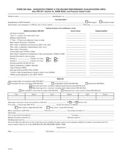
1 149 Chapter 10 advanced Welding SymbolsWeld all aroundField weldWeld lengthIntermittent weldSkip weldKey TermsSpacerConvex contourConcave contourFlush contourMelt-throughLearning ObjecTive Be able to interpret AWS welding symbols that include all of the information that could be used on themOverviewMany additional elements can be added to the basic parts of the AWS welding symbol. The additional elements and their placement, along with the basic parts of the welding symbol, are shown in Figures 10-1 and 10-2. They are described throughout the remainder of this aLL arOundThe specification to weld all around requires that the weld be made to encapsulate the entire joint.
2 In the case of a circular joint, the weld all around symbol is not required. The weld all around symbol consists of a circle that is placed over the intersection where the end of the reference line meets the arrow. Examples of weld all around welds and welding symbols are shown in Figures 10-3 and intermittent weldStaggered intermittent weldConsumable 14926/09/15 4:49 pm150 Chapter 10 Figure 10-1 AWS Standard Locations of the Elements of a Welding Symbol (AWS :2012, Figure 3 reproduced and adapted with permission from the American Welding Society (AWS), Miami, FL.)
3 Figure 10-2 AWS Supplementary Symbols (AWS :2012, Figure 2 reproduced and adapted with permis-sion from the American Welding Society (AWS), Miami, FL.) 15026/09/15 4:49 pm advanced Welding Symbols 151 FieLd weLdA field weld is defined by the American Welding Society (AWS) as [a] weld made at a location other than a shop or the place of initial construction. 1 The field weld symbol consists of a flag that is placed at the intersection where the end of the reference line meets the arrow (see Figure 10-5).1 AWS :2010, reproduced with permission from the American Welding Society (AWS), Miami, FLField weld SymbolsFigure 10-5 Field weld Symbol ExamplesWeld All Around SymbolsFigure 10-3 weld All Around SymbolsPLATE WELDED ON TOP OF ANOTHER PLATEBEAM WELDED TO A PLATECHANNEL WELDED TO A PLATEF igure 10-4 Example of weld All Around 15126/09/15 4:49 pm152 Chapter 10weLd LengThEach weld , with the exception of spot and plug welds, has a length component.
4 The weld length may be the entire length of the joint or some portion thereof. There are several different methods for providing the weld length information on a drawing. When the weld is to be the entire length of the joint, the length component is not required on the welding symbol. The welding symbol points to the joint requiring the weld , and the weld is made the entire length of that par-ticular joint, as shown in Figure 10-6. If a weld is required to make a change in di-rection, an additional welding symbol or a multi-arrow symbol should be the weld length is not required to extend the complete length of the joint, it can be defined by placing the required length to the right of the weld symbol.
5 The welding symbol then points to the area of the joint requiring the weld . It may replace the standard length dimension, as shown in Figure 10-6 Examples of Continuous 15226/09/15 4:49 pm advanced Welding Symbols 153 Placing section lines in the area where the weld is to be placed can also be used in combination with standard dimensions and welding symbols to iden-tify the required weld length and weld location. See Figure weLdsAn intermittent weld , also called a skip weld , consists of a series of welds placed on a joint, with unwelded spaces between each of the welds.
6 The indi-vidual weld segments in an intermittent weld have a length and pitch compo-nent. The weld length is the linear distance of each weld segment. The length is shown in the welding symbol to the right of the weld symbol. The pitch is the center-to-center distance of each of the weld segments. It is shown to the right of the length on the welding symbol, with a dash between the two. This concept is shown in Figure intermittent welds are placed on both sides of a joint, they can be either directly opposite each other, known as a chain intermittent weld , or they can be offset, known as a staggered intermittent weld .
7 The chain intermittent weld is shown in Figure 10-10. The staggered intermittent weld is shown in Figure 10-7 weld Length Specified on Welding Symbol Between Extension LinesFigure 10-8 weld Length Specified on Welding Symbol Between Extension Lines with Section Lines Representing the weld 15326/09/15 4:49 pm154 Chapter 10 Figure 10-9 Intermittent WeldFigure 10-10 Chain Intermittent WeldFigure 10-11 Staggered Intermittent 15426/09/15 4:49 pm advanced Welding Symbols 155weLd cOnTOur symbOLsThe contour of a weld refers to the shape of its face. A weld with a convex contour has a face that protrudes out in a convex shape from its toes; a weld with a concave contour has a face that is concave (sinks in from its toes); and a weld with a flush contour has a face that is flush with the base metal, or is flat from one toe to the other.
8 When required, the contour symbol is added to a welding symbol so that it is oriented to mimic the required contour of the weld (see Figure 10-12). When a contour symbol is not added to the welding symbol, standard welding and shop practices should be symbOLsPlacing a finish symbol adjacent to the contour symbol specifies the method of making the contour. The finish symbols are made up of letters. The letters and their corresponding methods are listed = unspecified This means that any appropriate method may be = grindingM = machiningC = chippingFigure 10-12 Contour 15526/09/15 4:49 pm156 Chapter 10R =rollingH =hammeringP =planishingSee Figure 10-13 for an example of a finish weLdsA welding symbol for a fillet weld includes the required fillet weld symbol and (as needed) the size, length, pitch, contour, method of making the contour, weld all around, field weld , and any other supplemental information listed in the tail of the welding symbol.
9 See Figure size of the fillet weld is shown to the left of the weld symbol. It rep-resents the length of the legs of the largest right triangle that can fit within the weld at it's smallest point, with the vertex of the triangle located at the intersec-tion of the two members being joined. See Figure 10-13 Examples of Contour Symbols with Method of FinishFigure 10-14 Example of a Welding Symbol for a fillet 15626/09/15 4:49 pm advanced Welding Symbols 157unequaL Leg fillet weLdsA fillet weld can be required to have unequal legs. In such cases, the size for each of the legs is shown on the welding symbol to the left of the weld sym-bol and is written in parentheses.
10 The only way to know which leg goes with which size is through either a detail drawing that shows the weld joint, as in Figure 10-16; a note; or other revealing information, such as one of the legs is required to be longer than one of the sides, as in Figure ThisThis Shown onthe DrawingVertexLargest Right TriangleThat Can Be Formed Within the WeldNote: When a fillet weld is measured,the measurement is taken at the locationwhere it is the 10-15 fillet weld SizeFigure 10-16 Unequal Leg fillet with Detail 15726/09/15 4:49 pm158 Chapter 10grOOve weLdsThe welding symbol for a groove weld may include, as needed, the groove weld symbol, size, depth of preparation, root opening, groove angle (also called included angle) contour, method of making the contour, length, pitch, weld all around, field weld , and any other supplemental information listed in the tail of the welding symbol.