Transcription of lecture 3 - Simulation and Timing in VHDL
1 EE 595 Part IIIS imulation and Timing in VHDLEE 595 EDA / ASIC Design LabSimulation Cycle in VHDLEE 595 EDA / ASIC Design LabFirst-Generation simulators used a technique CAD developers call a one-list algorithm,which is relatively fast but cannot handle parallel zero delay events such as exchangingAand example would not exchange the values of Aand B, but would give both Aand Btheold value of B, using one-list uses a two-list algorithm, which tracks the previous and new values of signals. In this method, expressions are first evaluated, then signals are assigned new values. InVHDL, the example code performs a data exchange between the two signals Aand Bat some point in Simulation time. In operation, the old values ofAand Bare fetched andscheduled for assignment, for zero delay, after a subsequent WAIT statement is <= B;zero delayB <= A;zero delayA <= B;zero delayB <= A;zero delaySimulation Cycle in vhdl (cont d)EE 595 EDA / ASIC Design LabThe ordering of zero delay events is handled with a fictitious unit called delta time.
2 Delta time represents the execution of a Simulation cycle without advancing Simulation AssignmentsProcess ExecutionSignal EvaluationsTimeEnterBeginMiddleEndLeaveA ll right-hand side assignments (evaluations) are calculated after assignments are Cycle in vhdl (cont d) The key points of Simulation and delta time are: The simulator models zero-delay events using delta time. Events scheduled at the same time are simulated in specific order during a delta time step. Related logic is then re-simulated to propagate the effects for another delta time time step. Delta time steps continue until there is no activity for the same instant of simulated 595 EDA / ASIC Design LabTiming Model of vhdl Simulation Cycle vhdl uses a Simulation cycle to model the stimulus and response nature of digital hardwareEE 595 EDA / ASIC Design LabStart SimulationStart SimulationUpdate SignalsUpdate Si gnalsExecute ProcessesExecute ProcessesEnd SimulationEnd SimulationDelayDelay Types All vhdl signal assignment statements prescribe an amount of time that must transpire before the signal assumes its new value This prescribed delay can be in one of three forms.
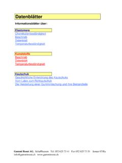
3 Transport-- prescribes propagation delay only Inertial-- prescribes minimum input pulse width and propagation delay Delta-- the default, if no delay time is explicitly specifiedEE 595 EDA / ASIC Design LabTransport Delay Delay must be explicitly specified by user Keyword TRANSPORT must be used Signal will assume its new value after specified delayEE 595 EDA / ASIC Design Lab-- TRANSPORT must be specifiedOutput <= TRANSPORT NOT (Input) AFTER 10 ns;-- TRANSPORT must be specifiedOutput <= TRANSPORT NOT (Input) AFTER 10 ns;InputOutputInputOutputInertial Delay Provides for specification of input pulse width, inertia of output, and propagation delay : Inertial delay is default and REJECT is optional :EE 595 EDA / ASIC Design Labtarget<= [REJECT time_expression] INERTIAL waveform;target<= [REJECT time_expression] INERTIAL waveform;Output <= not(Input) after10 ns;-- Propagation delay and minimum pulse width are 10nsOutput <= not(Input) after10 ns.
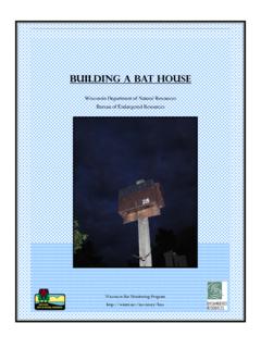
4 -- Propagation delay and minimum pulse width are 10nsInputOutputInputOutputInertial Delay (cont d) Example of gate with inertia smaller than propagation delay Inverter with propagation delay of 10ns which suppresses pulses shorter than 5ns Note that REJECT feature is new to vhdl 1076-1993EE 595 EDA / ASIC Design LabOutput <= REJECT 5ns INERTIAL not(Input) after10ns;Output <= REJECT 5ns INERTIAL not(Input) after10ns;InputOutput0 5 10 15 20 25 30 35 Delta Delay Default signal assignment propagation delay if no delay is explicitly prescribed vhdl signals assignment cannot take place immediately Delta is an infinitesimal vhdl time unit so that all signal assignments can result in signals assuming their values at some future time Supports a model of concurrent vhdl process execution The order in which processes are executed by simulator does not affect Simulation outputEE 595 EDA / ASIC Design LabOutput <= not(Input);-- Output assumes new value in one delta cycleOutput <= not(Input);-- Output assumes new value in one delta cycleDelta DelayAn Example Without Delta Delay What is the behavior of C?
5 EE 595 EDA / ASIC Design LabIN: 1->0 BCANAND gate evaluated first:IN: 1->0A: 0->1B: 1->0C: 0->0 NAND gate evaluated first:IN: 1->0A: 0->1B: 1->0C: 0->0 AND gate evaluated first:IN: 1->0A: 0->1C: 0->1 B: 1->0C: 1->0 AND gate evaluated first:IN: 1->0A: 0->1C: 0->1 B: 1->0C: 1->0 Delta DelayAn Example With Delta Delay What is the behavior of C?EE 595 EDA / ASIC Design LabIN: 1->0 BCAU sing delta delay schedulingUsing delta delay schedulingTimeDeltaEvent0 ns 1 IN: 1->0eval INVERTER2 A: 0->1eval NAND, AND3 B: 1->0C: 0->1eval AND4 C: 1->01 ns ATransport Versus Inertial Delay Inertial Delay Default in vhdl Can be similar to actual device behavior Spikes are swallowed Most commonly used in simulator Transport Delay Must specify with key word TRANSPORT Ideal delay.
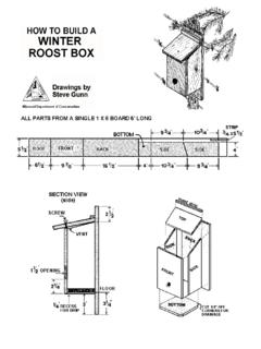
6 , passes any width pulse Good for wire delay and time 595 EDA / ASIC Design LabDelta Time Delta Time is a Simulation time cycle It is used to order sequential events during Simulation . More than one event can occur during a delta time. The time between any two sequential eventsis called a delta. These two events may be happening at the same real time but in a specific order, or they may be separated by a large real time during which time the circuit has been quiet A delta is the default value or if zero delay is specified as inA <= notB;These are the sameA <= notB after0 ns;EE 595 EDA / ASIC Design LabRelation Between Delta Delay and Real Time A combinational Circuit, in which all elements have zero delay, would settle down in 0 ns, but could occupy many 595 EDA / ASIC Design Lab161514 Relationship of41320deltas and real time391219268111815710170 ns10 ns 18 ns 24 ns 40 ns16151441320deltas and real time391219268111815710170 ns10 ns 18 ns 24 ns 40 nsDeltasTim