Transcription of Lecture 4 – Resistors - GM SYSTEMS LLC
1 Lecture 4 Resistors resistor characteristics. resistor types. Choosing Resistors . Introduction A resistor is not a pure resistance of exact value. A real resistor has a series A resistor is not a inductance and a parallel stray capacitance. These affect the behaviour of the pure resistance resistor , particularly at high frequencies. For Resistors we will: define the essential characteristics used to describe their performance;. present the main types of devices, differentiated by the materials and technologies used in manufacturing them, as these determine the characteristics;. compare the characteristics and recommend applications for different types of components. Analog Electronics Spring 2012. resistor Characteristics Resistors are the most commonly used passive electronic component. The characteristics and the features to consider when choosing a resistor are: resistance value, tolerance on value, stability, temperature coefficient, voltage coefficient, humidity effects, power dissipation, frequency effects, noise, reliability, size and packaging, availability and cost.
2 For insight into these factors, the materials and construction of the various resistor types must be considered. Tolerance on value Service variability of a resistor value is an overall, long-term value tolerance composed of factors such as purchase tolerance, ageing, stress and short-term excursions due to the local environment (temperature, humidity, etc). A. Component tolerances are resistor of, say, 10% rated tolerance can be selected to be within 1% of the tolerances at time of purchase required value when installed in a circuit, but such a resistor might well drift within (and often even outside) the rated 10% during its service. Hence, if either a very accurate or stable resistance value is required in a circuit, choose the right tolerance resistor when purchasing it, with a tolerance tighter than the required end-of-life tolerance.
3 Preferred Values and the Decade Progression Fundamental standardization practices require the selection of preferred values within the ranges available. Standard values may at first sight seem to be strangely numbered. There is, however, a beautiful logic behind them, dictated by the tolerance ranges available. The decade progression of preferred values is based on preferred numbers Component values generated by a geometric progression, repeated in succeeding decades. In have been standardized by the 1963, the International Electrotechnical Commission (IEC) standardized the IEC. preferred number series for Resistors and capacitors (standard IEC 60063). It is based on the fact that we can linearly space values along a logarithmic scale so a percentage change of a value results in a linear change on the logarithmic scale. Analog Electronics Spring 2012.
4 Recall that for a geometric progression, each individual term is given by: ( ). an ar n 1. where a n is the n-th term, a is the scale factor, and r is the common ratio. If r is chosen to be the k-th root of 10, and the scale factor is set to 100, then: an 100 k 10 n 1 ( ). Thus, the selection of k determines how many values of the geometric Component values progression there are in one decade. For example, if 6 values per decade are are spaced equidistantly on a logarithmic scale desired, k 6 and the common ratio is 6. 10 . The six rounded-off values become 100, 150, 220, 330, 470, 680. To figure out what tolerance is allowable on Resistors with these values, we can let the tolerance be . Then if we require successive values of Resistors to increase with almost certainty, then: an 1 an 1 1 . an 1 1 .. an 1 . 1 . k 10 . 1 . k 10 1 ( ). k 10 1.
5 Analog Electronics Spring 2012. For k 6 , we get . Thus, if we set the tolerance of Resistors with 6. values per decade to 20% , we get values that almost certainly increase, with minimal overlap: 100 20% = 80 to 120 330 20% = 264 to 396. 150 20% = 120 to 180 470 20% = 376 to 564. 220 20% = 176 to 264 680 20% = 544 to 816. The E' Series Values The IEC set the number of values for Resistors (and capacitors) per decade based on their tolerance. These tolerances are , 1%, 2%, 5%, 10%, 20%. and 40% and are respectively known as the E192, E96, E48, E24, E12, E6 and The E' series E3 series, the number indicating the quantity of values per decade in that values explained series. For example, if Resistors have a tolerance of 5%, a series of 24 values can be assigned to a single decade multiple ( 100 to 999) knowing that the possible extreme values of each resistor overlap the extreme values of adjacent Resistors in the same series.
6 Any of the numbers in a series can be applied to any decade multiple set. Thus, for instance, multiplying 220 by each decade multiple ( , 1, 10 100, 1000. etc.) produces values of 22, 220, 2 200, 22 000, 220 000 etc. The E' series of preferred resistor and capacitor values according to IEC 60063 are reproduced in Table Analog Electronics Spring 2012. 1% 2% 1% 2% 1% 2% 1% 2% 1% 2%. E192 E96 E48 E192 E96 E48 E192 E96 E48 E192 E96 E48 E192 E96 E48. 100 100 100 169 169 169 287 287 287 487 487 487 825 825 825. 101 172 291 493 835. 102 102 174 174 294 294 499 499 845 845. 104 176 298 505 856. 105 105 105 178 178 178 301 301 301 511 511 511 866 866 866. 106 180 305 517 876. 107 107 182 182 309 309 523 523 887 887. 109 184 312 530 898. 110 110 110 187 187 187 316 316 316 536 536 536 909 909 909. 111 189 320 542 920. 113 113 191 191 324 324 549 549 931 931.
7 114 196 328 556 942. 115 115 115 196 196 196 332 332 332 562 562 562 953 953 953. 117 198 336 569 965. 118 118 200 200 340 340 576 576 976 976. 120 203 344 583 988. 121 121 121 205 205 205 348 348 348 590 590 590. 123 208 352 597 5% 10% 20% 40%. 124 124 210 210 357 357 604 604 E24 E12 E6 E3. 126 213 361 612. 127 127 127 215 215 215 365 365 365 619 619 619 100 100 100 100. 129 218 370 626 110. 130 130 221 221 374 374 634 634 120 120. 132 223 379 642 130. 133 133 133 226 226 226 383 383 383 649 649 649 150 150 150. 135 229 388 657 160. 137 137 232 232 392 392 665 665 180 180. 138 234 397 673 200. 140 140 140 237 237 237 402 402 402 681 681 681 220 220 220 220. 142 240 407 690 240. 143 143 243 243 412 412 698 698 270 270. 145 246 417 706 300. 147 147 147 249 249 249 422 422 422 715 715 715 330 330 330. 149 252 427 723 360. 150 150 255 255 432 432 732 732 390 390.
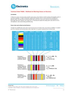
8 152 259 437 741 430. 154 154 154 261 261 261 442 442 442 750 750 750 470 470 470 470. 156 264 448 759 510. 158 158 267 267 453 453 768 768 560 560. 160 271 459 777 620. 162 162 162 274 274 274 464 464 464 787 787 787 680 680 680. 164 277 470 796 750. 165 165 280 280 475 475 806 806 820 820. 167 284 481 816 910. Table - IEC standard E' series of values in a decade Analog Electronics Spring 2012. marking Codes The IEC also defines how manufacturers should mark the values of Resistors and capacitors in the standard called IEC 60062. The colours used on fixed leaded Resistors are shown below: IEC labelling for leaded Resistors 4 bands 22 , 5%. 5 bands 2200 , 1%. 6 bands 100 k , , 15 ppm silver 10%. gold 5%. black 0 0 0 0 1 200 ppm brown 1 1 1 1 10 1% 100 ppm red 2 2 2 2 100 2% 50 ppm orange 3 3 3 3 1k 15 ppm yellow 4 4 4 4 10k 25 ppm green 5 5 5 5 100k blue 6 6 6 6 1M 10 ppm violet 7 7 7 7 10M 5 ppm grey 8 8 8 8 1 ppm white 9 9 9 9 Tolerance Multiplier Temperature Significant Figures Coefficient Figure Colour code marking of leaded Resistors The resistance colour code consists of three or four colour bands and is followed by a band representing the tolerance.
9 The temperature coefficient band, if provided, is to the right of the tolerance band and is usually a wide band positioned on the end cap. The resistance colour code includes the first two or three significant figures of the resistance value (in ohms), followed by a multiplier. This is a factor by Analog Electronics Spring 2012. which the significant-figure value must be multiplied to find the actual resistance value. ( the number of zeros to be added after the significant figures). Whether two or three significant figures are represented depends on the tolerance: 5% and wider require two band; 2% and tighter requires three bands. The significant figures refer to the first two or three digits of the resistance value of the standard series of values in a decade, in accordance with IEC 60063 as indicated in the relevant data sheets and shown in Table The colours used and their basic numerical meanings are recognized internationally for any colour coding used in electronics, not just Resistors , but some capacitors, diodes, cabling and other items.
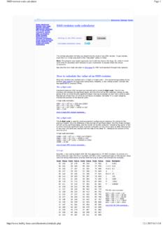
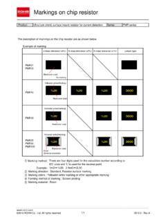
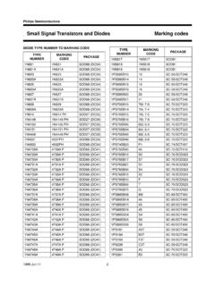
10 The colours are easy to remember: Black is the absence of any colour, and therefore represents the absence of any quantity, 0. White (light) is made up of all colours, and so represents the largest number, 9. In between, we have the The resistor colour code explained colours of the rainbow: red, orange, yellow, green, blue and violet. These take up the numbers from 2 to 7. A colour in between black and red would be brown, which has the number 4. A colour intermediate to violet and white is grey, which represents the number 8. Surface mount technology (SMT) chip Resistors are frequently marked with a three-digit number, and some typical values are shown in the table below. The first two numbers are the significant digits of the value, and the last digit is the multiplier (the number of zeros to add to the first two digits). For example, a chip resistor labelled 102 has a value of 1 k.