Transcription of Lecture 5: Filtration
1 Islamic University of Gaza Environmental Engineering DepartmentWaterTreatmentWater TreatmentEENV 4331 Lecture 5: FiltrationDr. Fahid Rabah15. Filtration in water Definition of Sedimentation: Filtration is a solid liquid separation process in which theliquid passes through a porous medium to remove asmuch fine suspended solids as Locations of Filtration tanks in water treatment: Filtration tanks are used in all types of water treatmentplants except for disinfection treatment plants. SeeFigures through illustrating the location of WaterPre SedimentationScreenCoagulationFlocculati onSedimentationDistributionDisinfectionS torageFiltrationFigure : Filtration Treatment Plant(River Water)3 ScreenSurface waterSdi ttiCoagulationFlocculationSedimentationD istributionDisinfectionStorageFiltration Figure : Filtration Treatment Plant4 Ground WaterWaterRapid Mixing FlocculationSedimentationRecarbonationDi stributionDisinfectionStorageFiltrationF igure : Softening Treatment Plant Single stage softeningsoftening5 Ground Water wellFiltrationAerationDistributionDisinf ectionStorageFigure : Aeration Treatment Plant(ironandmanganeseremovalplant)( iron and manganeseremoval plant)65.
2 Filtration in water Treatment53 Needforfiltration: Settling is not sufficient to remove all particles and :flocs from water. Filtration Needed for fine particles not removed by di t tisedimentation. Filters can also capture Giardia cysts, viruses, and asbestosfibersasbestos fibers Typical overflow qualities from sedimentation tanks range from 1 to 10 NTU. Filtration , usually rapid sand Filtration , is then employed for further polishing , to get the turbiditytolowerthan05 NTU(asrequiredbyturbidity to lower than NTU (as required by legislation). Rapidsandfiltrationafterpriorsedimentati onisthe7 Rapid sand Filtration after prior sedimentation is the most common configuration worldwide5. Filtration in water Types of filters used in water treatment: granular material filters are the most used types of filtersin water treatment. Usuallysand, anthracite, and are three types of granular filters:1. Single medium filters :onetypeofmediaisused:eithersandoranthra citeonetypeofmediaisused:eithersandorant hracite2.)
3 Dual media filters: two types of media is used usually sandandanthraciteandanthracite3. Multimedia filters: three types of media are used usuallysand , anthracite , and Filtration in water Geometryand components of Rapid Sand Filter:ypp Rapid sand filters are always rectangular tanks. Figures to show typical Rapid sand filters used inwater treatment. MaincomponentsofRapidsandfilterare: MaincomponentsofRapidsandfilterare:1. A concrete tank2. Filter Backwash system: pressurized water and air lines9 Figure : Rapid sand filter components10 Figure : Rapid sand filter components :with gravel and 11ppgperforated pipes under drain systemFi56b12 Figure : Rapid sand filter components :with gravel and perforated pipes under drain systemFigure : Rapid sand filter components :with gravel and 13ppgperforated pipes under drain systemFi5814 Figure : Rapid sand filter components: with ducts under drain system15 Figure : Rapid sand filter components: with nozzle under drain system5.
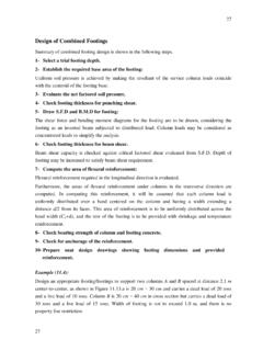
4 Filtration in water :Figure : Rapid sand filter perforated slab and nozzle under drain system165. Filtration in water TreatmentFigure : NozzleusedinRapidsandfilterNozzle used in Rapid sand filterunder drain system175. Filtration in water Operation of Rapid Sand Filter:TherearetwomodesofoperationofRapi dsandfilterTherearetwomodesofoperationof Rapidsandfilter Filtration mode ( see Figure ) Backwashing mode ( see Figure )185. Filtration in water Treatment57 Filtrationmode: Water flows downward through a bed Filtration mode:of sand and gravel Particlesarecapturedonandbetween Particles are captured on and between sand grains Filtered water is collected in the under drain,senttodisinfectiondrain, sent to disinfection195. Filtration in water Treatment58 Backwashmode: Backwash mode: Sand is backwashed when It becomes clogged, or Turbidity of filtered water gets too high Duringbackwash,waterispumpedDuring backwash, water is pumped upwards through the sand bed205. Filtration in water Treatment Sand becomes fluidized , and particles are flushed from the sand Dirty backwash water is pumped into a settlingpondandeithersettling pond, and either Recycled back into plant, orDid Disposed Backwashing can consume 1% to 5% of a plant s production2122 Figure : Rapid sand filter during filtration23 Figure : Rapid sand filter during backwashing5.
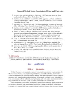
5 Filtration in water Filter media properties24 Figure : filter media grain distribution5. Filtration in water Treatmenthflddhdhl These filters use sand and crushed anthracite coal on a graded gravel base. media layers are arranged in a course to fine gradation in the direction of flow, which allows greater depth of penetration of flocparticles. p Multimedia filters are selected with specific gravities so that moderateintermixingbetweenmedialayersocc ursduringmoderate intermixing between media layers occurs during Filtration in water Filter media propertiesThe filter media is characterized by two main parameters:theeffectivesizeandtheuniform ityEffective size of the filter mediaparameters: the effective size and the uniformity tiifthdiithdi tThe effective size of the media is the diameter that 10% of the filter media is less than it size and is denoted as d10. 60ddU Uniformity coefficient of the filter media10dU =Uniformity coefficientd60= sieve size that passes 60% by weightd10= sieve size that passes 10% by weight d60 and d10are found by sieve analysis of the media to be used in the filter.
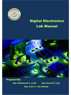
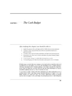
6 26 Another important sieve size is d90 that is usedto calculate the backwash Filtration in water Treatment27 Figure : Rapid sand media layersFigure : Rapid sand medialayersmedia layers285. Filtration in water Filtration in water TreatmentTable52 Table Filtration in water Filtration in water TreatmentFigure : Head loss and effluent turbidity increase with time during filtration32yg5. Filtration in water TreatmentFigure : Head loss in rapid sand filterduringfiltrationcycle33filter during Filtration cycleFigure : Head loss in rapid sand filter34gpHead loss in a clean filterCarmen Kozeny equation:2 vAVgkLh232)1( dAV 6 sAQv Where,k =dimensionless coefficient , 5 for sand, 6 for anthracite;vfiltrationratem3/m2dorfiltra tionvelocitym/d sv = Filtration rate m3 , or Filtration velocity m/d. A = the grain surface area;As = surface area of the sand filter;V=thegrainvolume;V= the grain volume; = filter porosity; around for sand filterФ= shape factor ; 1 for spherical particles, for sand; =dynamicviscosity;Ns/m235 =dynamic viscosity; = water density; kg/m3h=head loss in clean filter,mExample :A dual media filter is composed of m anthracite (mean particle size ) that is placed over a m layer of sand (mean particle size ) /with a Filtration rate of m/h.
7 Assume the grain sphericity ф= and porosity ( ) = for both. Estimate the headloss in the clean filter at itlA. Head loss in the anthracite *0020*7506400*1000*819) (* *6* B. Head loss in the sand * *1000* * * *1000* ) (* *5* B. Head loss in the sand 36 Head loss during Filtration (Nonecleanfilter)(None clean filter) Where filterdtlbVavh Where,v = Filtration rate m3 , or Filtration velocity m/d. a ,b = coefficients depending on the filter media properties;Vfilt d=filteredvolumeperunitareaoffiltersince lastbackwash;m3/m2 Vfiltered filtered volume per unit area of filter since last backwash; m/m(hl)t= head loss at any time (t), m 37 Example :A filter has a head loss of m when clean ( newly washed), and m after 24 hrs of Filtration at a rate of Estimate the head loss both immediately after backwash and 10 hrs later, if the Filtration rate is changed to 2 . A. Estimate the values of a and b : 0* 3600*24* * solving the 2 equations simultaneously , a= 200, b = Calculate head loss for the new flow rate: 2 *200100020 *10*10002* 381000100010 Filtration hydraulics Calculations39 Filtration hydraulics Calculations40 Filtration hydraulics Calculations41 Calculations of filter backwash rate The backwash flow rate is calculated using the following equations: 3d 2390 gsdGn Where,bk ht3/2d vb= backwash rate m3 ,d90=sieve size that passes 90% by weight =dynamic viscosity; =waterdensity;kg/m3 =water density; kg/m3 s= filter particles density.
8 Kg/m3Gn=Galileo number, dimensionlessg=gravitationalacceleration m/s2 42g =gravitational acceleration, m/sCalculations of filter expansionThe expansion during backwash is calculated using the following equations:q eeLL 11 sdesignbevv sWhere,L =bed depth during Filtration , mL=expandedbeddepthmLe= expanded bed depth, m e= expanded bed porosity, dimensionless = bed porosity during Filtration , dimensionlessv=settlingvelocityofthefilt erparticlesm/svs= settling velocity of the filter particles, m/s43 Calculations of headloss during filter backwashHeadloss during backwashing is calculated using the following equation:q seeLh1 Where,Le= expanded bed depth, m e= expanded bed porosity, dimensionlessdk/3 = water density; kg/m3 s= filter particles density; kg/m344 Backwash hydraulics Calculations45 Backwash hydraulics Calculations46 Backwash hydraulics Calculations47 Backwash hydraulics Calculations48 Filtration hydraulics Calculations49 Filtration hydraulics Calculations50 Filtration hydraulics Calculations51