Transcription of Lecture 9 Detailing - PHG - A1 - Rev 12 - 16 Nov 17 ...
1 EC2 Webinar Autumn 2017 Lecture 9/1 DetailingLecture 916thNovember 2017 Reinforced Concrete Detailing to Eurocode 2EC2 Section 8 - Detailing of Reinforcement - General Rules Bar spacing, Minimum bend diameterAnchorage of reinforcementLapping of barsLarge bars, bundled barsEC2 Section 9 - Detailing of Membersand Particular rules BeamsSolid slabs Flat slabsColumnsWallsDeep beamsFoundationsDiscontinuity regionsTying SystemsEC2 Webinar Autumn 2017 Lecture 9/2 Clear horizontal and vertical distance , (dg+5mm)or 20mm For separate horizontal layers the bars in each layer should be located vertically above each other.
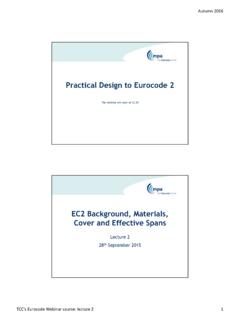
2 There should be room to allow access for vibrators and good compaction of 8 - General RulesSpacing of barsEC2: Cl. : Min75 mm gap To avoid damage to bar is Bar dia 16mmMandrel size 4 x bar diameterBar dia > 16mmMandrel size 7 x bar diameterThe bar should extend at least 5 diameters beyond a bend Minimum mandrel size, mMin. Mandrel Dia. for bent barsEC2: Cl. : mBS8666 alignsEC2 Webinar Autumn 2017 Lecture 9/3 Minimum mandrel size, m To avoid failure of the concrete inside the bend of the bar: m,min Fbt ((1/ab) +1/(2 )) / fcdFbt ultimate force in a bar at the start of a bendab for a given bar is half the centre-to-centre distance between bars.
3 For a bar adjacent to the face of the member, abshould be taken as the cover plus /2 Mandrel size need not be checked to avoid concrete failure if : anchorage does not require more than 5 past end of bend bar is not the closest to edge face and there is a cross bar inside bend mandrel size is at least equal to the recommended minimum valueMin. Mandrel Dia. for bent barsEC2: Cl. : stress inside bendsAnchorage of reinforcementEC2: Cl. Webinar Autumn 2017 Lecture 9/4 The design value of the ultimate bond stress, fbd= 1 2fctdwhere fctdshould be limited to C60/75 1 = 1 for good and for poor bond conditions 2= 1 for 32, otherwise (132- )/100 Ultimate bond stressEC2: Cl.
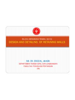
4 : bond stressEC2: Cl. , Fig : and bad bond conditionsTop is poor Bond conditionunhatched zone good bond conditionshatched zone - poor bond conditions EC2 Webinar Autumn 2017 Lecture 9/5lb,rqd= ( / 4) ( sd/fbd)where sd= the design stress of the bar at the position from where the anchorage is required anchorage lengthEC2: Cl. : bent bars lb,rqdshould be measured along the centreline of the barEC2 Figure Fig 1 2 3 4 5lb,rqd lb,minHowever: ( 2 3 5) ,min> max( ,rqd; 10 , 100mm) design Anchorage Length, lbdEC2: Cl. : values are in EC2: Table calculate 2and 3 Table requires values for:CdValue depends on cover and bar spacing, see Figure depends on position of confinement reinforcement,see Figure = ( Ast Ast,min)/ As Where Astis area of transverse Webinar Autumn 2017 Lecture 9/6 Table - Cd& K factorsConcise: Figure : Figure : Figure corner bar?
5 Table - Other than straight shapesConcise: Figure : Figure Webinar Autumn 2017 Lecture 9/7 Alpha valuesEC2: Table : 1 2 3 4 5 Anchorage of links Concise: Fig : Cl. Webinar Autumn 2017 Lecture 9/8 LapsEC2: Cl. 1 2 3 5 6lb,rqd l0,min 6= ( 1/25)0,5but between and where 1is the % of reinforcement lapped within the centre of the lapPercentage of lapped bars relative to the total cross-section area< 25%33%50%>50% : Intermediate values may be determined by interpolation. 1 2 3 5are as defined for anchorage lengthl0,min max{ 6 lb,rqd; 15 ; 200} design Lap Length, l0( )EC2: Cl.
6 , Table : Webinar Autumn 2017 Lecture 9/9 Arrangement of LapsEC2: Cl. , Fig exampleAnchorage and lap lengthsEC2 Webinar Autumn 2017 Lecture 9/10 Anchorage Worked ExampleCalculate the tension anchorage for an H16 bar in the bottom of a slab:a)Straight barsb)Other shape bars (Fig b, c and d)Concrete strength class is C25/30 Nominal cover is 25mmAssume maximum design stress in the barBond stress, fbdfbd= 1 2fctdEC2 Equ. 1= Good bond conditions 2= bar size 32fctd= ctfctk,0,05/ c EC2 cl (2), Equ ct= c = ,0,05 = x fck2/3EC2 Table x 252/3= MPafctd= ctfctk,0,05/ c = = x = MPaEC2 Webinar Autumn 2017 Lecture 9/11 Basic anchorage length, lb, ( /4) ( sd/fbd)EC2 Equ stress in the bar, sd= fyk/ s= 500 = ( /4) ( 435 ) = For concrete class C25/30 design anchorage length, lbdlbd= 1 2 3 4 lb,minlbd= 1 2 3 4 5( ) For concrete class C25/30EC2 Webinar Autumn 2017 Lecture 9/12 Alpha valuesEC2: Table : - Cd& K factorsConcise: Figure.
7 Figure : Figure Webinar Autumn 2017 Lecture 9/13 design anchorage length, lbdlbd= 1 2 3 4 lb,minlbd= 1 2 3 4 5( ) For concrete class C25/30a) Tension anchorage straight bar 1= 3 = conservative value with K= 0 4= N/A 5= conservative value 2= (Cd )/ 2= (25 16)/16 = x = = 592mmDesign anchorage length, lbdlbd= 1 2 3 4 lb,minlbd= 1 2 3 4 5( ) For concrete class C25/30b) Tension anchorage Other shape bars 1= Cd= 25 is 3 = 3 x 16 = 48 3 = conservative value with K= 0 4= N/A 5= conservative value 2= (Cd 3 )
8 / 2= (25 48)/16 = x = = 646mmEC2 Webinar Autumn 2017 Lecture 9/14 Worked example - summaryH16 Bars Concrete class C25/30 25 Nominal coverTension anchorage straight bar lbd= = 592mmTension anchorage Other shape bars lbd= = 646mmlbdis measured along the centreline of the barCompression anchorage ( 1 = 2= 3 = 4= 5= )lbd= = 646mmAnchorage for Poor bond conditions, lbd= Good value length, l0= anchorage length x 6 Anchorage & lap lengthsHow to design concrete structures using Eurocode 2 Column lap length for 100% laps & grade C40/50 = x 61Ф = ФEC2 Webinar Autumn 2017 Lecture 9/15 Table.
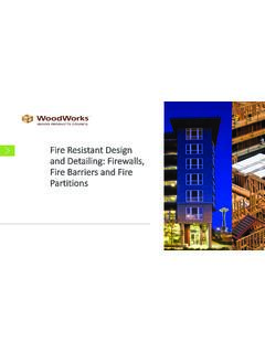
9 Typical values of anchorage and lap lengths for slabsBond Length in bar diametersconditionsfck /fcu25/30fck /fcu28/35fck /fcu30/37fck /fcu32/40 Full tension and compression anchorage length, lbd good 40373634 poor 58535149 Full tension and compression lap length, l0 good 46434239 poor 66615956 Note: The following is assumed:- bar size is not greater than 32mm. If >32 then the anchorage and lap lengths should beincreased by a factor (132 - bar size)/100- normal cover exists- no confinement by transverse pressure- no confinement by transverse reinforcement- not more than 33% of the bars are lapped at one placeLap lengths provided (for nominal bars, etc.)
10 Should not be less than 15 times the bar sizeor 200mm, whichever is /lap lengths for slabsManual for the design of concrete structures to Eurocode 2 Laps between bars should normally be staggered and not located in regions of high of laps should comply with Figure :All bars in compression and secondary (distribution) reinforcement may be lapped in one of LapsEC2: Cl. : Cl a is used in cl (3),Transverse reinf. EC2 Webinar Autumn 2017 Lecture 9/16 FThere is transverse tensionStrut-and-tie modelsSTM models help us understand: The anchorage of bars Any Transverse reinforcement provided for other reasons will be sufficient if the lapped bar < 20mm or laps< 25% If the lapped bar 20mmthe transverse reinforcement should have atotal area, Ast 1,0 Asof one spliced bar.