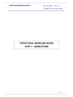
Transcription of Practical Design to Eurocode 2
1 EC2 Webinar Autumn 20177/1 Practical Design to Eurocode 2 Lecture 7 ColumnsThe webinar will start at order effectsWhat other 1storder effects are there?What is MEd?ColumnsLecture 72ndNovember 2017EC2 Webinar Autumn 20177/2 The Column Design ProcessAllow for imperfectionsin the columnDetermine slenderness, , via effective length loDetermine slenderness limit, limIs lim?YesNoColumn is not slender, MEd = Max (M02, NEde0)Column is slenderMEd = Max(M02;M0e+M2;M01+ ;NEde0)Calculate As( using column chart)Check detailingrequirementsDetermine the actionson the columnActionsActions on the columns are determined using one of the analysis methods we looked at for flexural the analysis obtain the following data: Ultimate axial load, NEd Ultimate moment at the top of the column,Mtop Ultimate moment at the bottom of the column,MbottomOther first order effects are due to geometric order effects, effects due to changes in geometry, can be significant in columns.
2 Ie slender columnsEC2 Webinar Autumn 20177/3 Geometric ImperfectionsCl. in cross-section dimensions are normally taken into account in the material factors and should not be included in structural need not be considered for out-of-plumb needs to be considered and is represented by an inclination, i i= 0 h mwhere 0= 1/200 is the basic value h = 2/ l; 2/3 h 1 m= ( (1+1/m))where l = the length or height [m]m = no. of vert. members(see (6))For isolated columns in braced systems, mand hmay be taken as i= 0 = 1/200 ActionsEffective length, l0 ImperfectionsSlenderness, Slenderness limit, limIs lim?YesNoDesign Moments, MEdSlen-derCalculate AsDetailingCl. (7) & (9) isolated members at ULS, the effect of imperfections may be taken into account in two ways:a) as an eccentricity, ei= il0/2So for isolated columns in a braced system, ei= l0/400 may be ) as a transverse force, HiHi = iNfor un-braced membersHi= 2 iNfor braced members= N/100 Geometric ImperfectionsEC2 Webinar Autumn 20177/4EC 2:Concise:UnbracedBracedExamples of Isolated MembersFigure compression members are subject to a Minimum Eccentricity:e0= h/30 but 20 mmGeometric Imperfections:Cl (4)EC2 Webinar Autumn 20177/5M01= Min{|Mtop|,|Mbottom|} + eiNEdM02= Max{|Mtop|,|Mbottom|} + eiNEdei= lo/400 NEd= Design load in the columnFor a stocky column, Design momentMEd= Max{M02, e0 NEd}e0= Max{h/30,20mm} Design Moments Stocky ColumnsOnly 1storder momentsM01= Min{|Mtop|,|Mbottom|} - eiNEdM02= Max{|Mtop|,|Mbottom|} + eiNEdNote: in the next revision of How to Design Structures using EC2 the calculation of M01will change.
3 The sign before eiNEd will change from positive to Moments Stocky ColumnsOnly 1storder momentseiNEdM02MM01EC2 Webinar Autumn 20177/6 Moments in Slender ColumnsCl. Moment,MEd = Max {M02;M0e + M2; M01 + ;NEde0}EC 2:Concise:Second order effects may be ignored if they are less than 10% of the corresponding first order effectsSecond order effects may be ignored if the slenderness, is less than limwhere lim= 20 A B C/ nWith biaxial bending the slenderness should be checked separately for each direction and only need be considered in the directions where limis exceededIs the Column Slender?Cl. , length, l0 ImperfectionsSlenderness, Slenderness limit, limIs lim?YesNoDesign Moments, MEdSlen-derCalculate AsDetailing2ndorder effectsEC2 Webinar Autumn 20177/7EC 2:Concise:26 Slenderness, = l0/il0=effective length = (l = actual length)i = radius of gyration = (I/A)hence for a rectangular section = l0 / h for a circular section = 4 l0 / h ActionsEffective length, l0 ImperfectionsSlenderness, Slenderness limit, limIs lim?
4 YesNoDesign Moments, MEdSlen-derCalculate AsDetailingSlendernessEC 2:Concise:27 ActionsEffective length, l0 ImperfectionsSlenderness, Slenderness limit, limIs lim?YesNoDesign Moments,MEdSlen-derCalculate AsDetailingl0= l l0= 2l l0= 0,7l l0= l / 2 l0= l l /2 <l0< l l0> 2l ++ ++221145,0145,01kkkkF= 0,5 Braced members:Unbraced members: ++ +++ + kkkk kkkk 221121211111;101maxF = M Figure , , k= ( / M) (E / l)Effective length, l0= FlEffective lengthFig (f)Fig (f)Fig (g)Fig (g)EC2 Webinar Autumn 20177/8EC 2:Concise:Failing columnNon failing columnk1at End 1k2at End 2 Non failing columnFrom PD 6687 The contribution of non failing columns to the joint stiffness may be ignored For beams /Mmay be taken as l/2EI(allowing for cracking in the beams) k1= [EI`/`l]col/ [ 2EI/l]beams1k2= [EI`/`l]col/ [ 2EI/l]beams2 Assuming that the beams are symmetrical about the column and their sizes are the same in the two storeys shown, then:k1= k2= [EI/`l]col/ [2 x 2EI/l]beams 6687 length & kfactorsEC 2:Concise:29 Slenderness = l0/i wherel0= FlActionsEffective length, l0 ImperfectionsSlenderness, Slenderness limit, limIs lim?
5 YesNoDesign Moments, MEdSlen-derCalculate ====blElEkbccIIi = (I/A)for a rectangular section = l0/ h for a circular section = 4 l0/ hk = relative stiffnessFCl. length & SlendernessEC2 Webinar Autumn 20177/9EC 2:Concise:30 Allowable Slenderness lim= 20 A B C/ nwhere:A= 1 / (1+ ef) efis the effective creep ratio;(if efis not known, A= 0,7 may be used)B = (1 + 2 ) = Asfyd/ (Acfcd)(if is not known, B= 1,1 may be used)C = -rmrm= M01/M02 M01, M02are first order end moments, M02 M01 (if rmis not known, C= may be used)n= NEd/ (Acfcd)ActionsEffective length, l0 First order momentsSlenderness, Slenderness limit, limIs lim?YesNoDesign Moments, MEdSlen-derCalculate AsDetailingSlenderness limitCl. 2:Concise:105 kNm105 kNm105 kNm-105 kNm105 kNmrm= M01/ M02= 0 / 105 = 0C= 0= M01/ M02= 105 / -105 = -1C= + 1= M01/ M02= 105 / 105= 1C= 1= lim= 20 A B C/ nFactor CCl.
6 Webinar Autumn 20177/10EC 2:Concise:Factor CCl. = -rmrm= M01/M02 Note:In the following cases, rmshould be taken as ( C= ) for braced members in which the first order moments arise only from or predominantly due to imperfections or transverse loading For unbraced members in generalConservatively, use the value ofM01that gives the largest positive value for rmand hence the smallest value for 2:Concise:ActionsEffective length, l0 ImperfectionsSlenderness, Slenderness limit, limIs lim?YesNoDesign Moments, MEdSlen-derCalculate AsDetailingIs l0/i= lim= 20 A B C/ n ?Is lim?EC2 Webinar Autumn 20177/11EC 2:Concise:ActionsEffective length, l0 ImperfectionsSlenderness, Slenderness limit, limIs lim?YesNoDesign Moments, MEdSlen-derCalculate AsDetailingNo, < limM01= Min{|Mtop|,|Mbottom|} + eiNEdM02= Max{|Mtop|,|Mbottom|} + eiNEdei= lo/400 NEd= Design load in the columnFor a stocky column, Design momentMEd= Max{M02, e0 NEd}e0= Max{h/30,20mm} Design Moments Stocky Columns (aka 1storder moments and effects of imperfections)As before !
7 EC 2:Concise:2ndorder effectsThe methods of analysis include a general method, for 2ndorder effects based on non-linear second order analysis and the following two simplified methods: Method based on nominal stiffness Method based on nominal curvatureThis method is primarily suitable for isolatedmembers with constant normal force anddefined effective length. The method gives anominal second order moment based on adeflection, which in turn is based on theeffective length and an estimated , cl (preferred in UK)ActionsEffective length, l0 ImperfectionsSlenderness, Slenderness limit, limIs lim?YesNoDesign Moments, MEdSlen-derCalculate AsDetailingYes, limEC2 Webinar Autumn 20177/12 Typical unbraced columnTypical braced column1st Ordermoments2nd OrdermomentsCombinationof moments1st Ordermoments2nd OrdermomentsCombinationof momentsMoments in Slender Columns 0000EC 2:Concise:MEd= M0Ed+ M2M0 Edis the 1storder moment including the effect of imperfectionsM2is the nominal 2ndorder 1storder end moments M01and M02 may be replaced by an equivalent 1storder end moment M0e:M0e= ( + ) , this is only the mid-height moment the two end moments should be considered too.
8 PD 6687 advises for braced structures:MEd= Max {M02, M0e+M2; M01+ } e0 NEdwhere M02 = Max{|Mtop|;|Mbot|} + eiNEdM01 = Min {|Mtop|;|Mbot|} + eiNEdNominal Curvature MethodCl. Mbotare frame analysis 1storder end momentsEffectively:MEd= Max {M02, M0e+M2; M01+ ; e0 NEd}EC2 Webinar Autumn 20177/13e2= (1/r)l02/c1/r = KrK /r0Kr = (nu n)/(nu-nbal) 1 (or see Column charts)n = NEd/(Acfcd)nu= 1 + = Asfyd/(Acfcd)nbal= = 1 + ef 1 = + fck /200 /150 Second order momentCl. = NEde2c = 10 (for a constant cross section)1/r0= yd /( ) yd = fyd/EsMoments in Slender ColumnsCl. Moment,MEd = Max (M02, M0e + M2, M01 + ,NEde0)Can be used genericallyEC2 Webinar Autumn 20177/14EC 2:Concise:ActionsEffective length, l0 ImperfectionsSlenderness, Slenderness limit, limIs lim?YesNoDesign Moments, MEdSlen-derCalculate AsDetailingdhAs2 ApAs1 pud s , p c0c2 ( ) c3cu2 ( ) cu3 A B C (1- c2/ cu2)hor(1- c3/ cu3)h p(0) yreinforcing steel tension strain limitconcrete compression strain limitconcrete pure compression strain limitCBAS ection Design :Bending with/without Axial LoadEC2 Figure Figure of Design :dhAs2 ApAs1 pud s , p c0c2 ( ) c3cu2 ( ) cu3 A B C (1- c2/ cu2)hor(1- c3/ cu3)h p(0) yreinforcing steel tension strain limitconcrete compression strain limitconcrete pure compression strain limitCBAEC2 Figure Figure of Design :Pure compressionPure flexureSection Design :Bending with/without Axial LoadEC2 Webinar Autumn 20177/15 Section Design :Bending with/without Axial LoadDesignEither: iterate such that AsN= AsM For axial loadAsN/2 = (NEd cchfckbdc/ c)/( sc st) For momentAsM/2 = [MEd cchfckbdc(h/2 dc/2)/ c]/[(h/2 d2)( sc+ st)Or.]
9 Calculate d2/h, NEd/bhfckand MEd/bh2fckAnd use column charts ..To find Asfyk/bhfckand thus AsConcise , Design Chart-Figure Webinar Autumn 20177/16 Column Design Chart-Figure BendingCl. ,0 + For rectangular cross- NRd= Acfcd+ AsfydFor circular cross-sectionsa = done the analysis and Design one way, you have to do it in the other direction and check biaxial bending. Often it will be non-critical by inspection but one should check ..Note: imperfections need only be taken in the one, more critical direction so either MEdzor MEdymight be reduced in this checkEC2 Webinar Autumn 20177/17 NRdNEdMEdzMEdya = 2a = 1a = bending for a rectangular columnActionsEffective length, l0 ImperfectionsSlenderness, Slenderness limit, limIs lim?YesNoDesign Moments, MEdSlen-derCalculate AsDetailing h 4b (otherwise a wall) min 12 As,min = 0,10 NEd/fydbut 0,002 Ac As,max = Ac (0,08 Acat laps) Minimum number of bars in a circular column is 4.
10 Where direction of longitudinal bars changes more than 1:12 the spacing of transverse reinforcement should be calculated. Details/Detailing EC2 ( )EC2 Webinar Autumn 20177/18 Link spacingscl,tmax = min {20 min; b ; 400mm} 150mm 150mmscl,tmaxbut scl,tmaxshould be reduced by a factor : in sections within h above or below a beam or slab near lapped joints where > ,tmax= min {12 min; ; 240mm}A min of 3 links are required in lap lengthLinksEC2 ( )No compression bar > 150 mm from a restraining barLink diam= max (6, max/4)(For HSC columns see NA)The Column Design ProcessAllow for imperfectionsin the columnDetermine slenderness, , via effective length loDetermine slenderness limit, limIs lim?YesNoColumn is not slender, MEd = Max (M02, NEde0)Column is slenderMEd = Max(M02;M0e+M2;M01+ ;NEde0)Calculate As( using column chart)Check detailingrequirementsDetermine the actionson the columnEC2 Webinar Autumn 20177/19 Column Worked ExampleWorked ExampleThe structural grid is m in each direction.