Transcription of Level sensor Magnetostrictive, high-resolution …
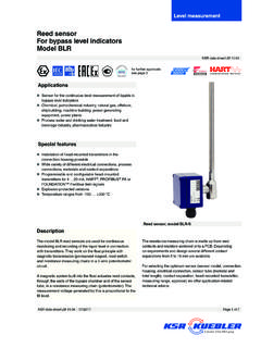
1 KSR data sheet FFG-P, FFG-T, FFG-TP, FLM-HPage 1 of 9A division of the WIKA Group Level sensorMagnetostrictive, high-resolution measuring principleModels FFG-P, FFG-T, FFG-TP, FLM-HData sheets showing similar products: Level sensor , with reed chain technology; see model FLRA pplications High-accuracy Level measurement for almost all liquid media Chemical, petrochemical, natural gas, off shore, shipbuilding, machine building, power generating equipment, power plants Process water and drinking water treatment, food industry, pharmaceutical industrySpecial features Process- and system-specifi c solutions possible Operating limits: - Operating temperature: T = -90.
2 +400 C- Operating pressure: P = Vacuum to 100 bar- Limit density: 400 kg/m3 Resolution < mm Wide variety of diff erent electrical connections, process connections and materials Explosion-protected versionsDescriptionThe model FFG-P, FFG-T, FFG-TP and FLM-H sensors are used for the high-accuracy, continuous Level measurement of liquids and are based on determining the position of a magnetic fl oat according to the magnetostrictive measuring measurementLevel sensorModel FFG-T, fl ange connectionModelDescriptionFFG-PStandard versionFFG-THigh-temperature versionFFG-TPPlastic versionFLM-HSterile versionKSR data sheet LM 09/2015 Page 2 of 9 KSR data sheet LM 09/2015 Further special features Large scope of application due to the simple, proven functional principle Process connection, guide tube and float from stainless steel , , or plastic For harsh operating conditions, long service life Continuous measurement of levels.
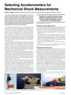
3 Independent of physical and chemical changes of the media such as: Foaming, conductivity, dielectric constant, pressure, vacuum, temperature, vapours, condensation, bubble formation, boiling effects, density change Signal transmission over long distances Simple installation and commissioning, onetime calibration only, no recalibration necessary. Level displayed proportional to volume or height Parallel measurement of interface layer and overall Level possible via HART interfaceOptions Customised solutions Process connection, guide tube material and float from special steel, titanium, Hastelloy (others on request) In combination with limit switch, stepless setting of the limit values over the entire measuring rangeIllustration of the principleDesign and operating principle The measuring process is triggered by a current impulse.
4 This current produces a circular magnetic field (3) along a wire (1) made of magnetostrictive material fixed in the guide tube. At the point being measured (liquid Level ) there is a float with permanent magnets (4) acting as a position transducer. The interaction of both magnetic fields generates a mechanical torsion wave (5) in the wire. This is converted into an electrical signal at the end of the wire in the sensor housing (2) by a piezoceramic converter. The measured propagation delay enables the origination point, and thus the float position, to be determined with high Wire2 sensor housing3 Magnetic field4 Permanent magnet5 Torsional waveKSR data sheet LM 09/2015 Page 3 of 9 Product overviewSensor modelAproval (Option)withoutEx iEx d3 AFFG-PxxxFFG-TxxFLM-HxxSensor modelDescriptionMaterialsTemperature range(process)Stainless steel (316Ti)Stainless steel (316L)Titanium (grade 2)Stainless steel (316L)
5 PPPVDFFFG-PMagnetostrictive sensor , standardxxx-60 .. +185 CFFG-TMagnetostrictive sensor , high temperaturexxx-90 .. +400 CFFG-TPMagnetostrictive sensor , plasticxx-10 .. +100 CFLM-HMagnetostrictive sensor , sterile versionxx-40 .. +400 CType approvalApprovalModelApproval N RU Sanitary Standards 74-06Ex approvalsExplosion protectionIgnition protec-tion typeModelZoneApproval numberATEXEx iFFG-T-Ex iZone 0 IBExU 02 ATEX 1124 X II 1/2G Ex ia IIC T3 .. T6Ex 0 ZELM 10 ATEX 0439 II 1/2G Ex ia IIC T3 .. T6Ex 1 ZELM 13 ATEX 0508 X II 1/2G Ex d IIB T3 to T6 Ga GbPage 4 of 9 KSR data sheet LM 09/2015 sensor , standard, model FFG-PProcess connection, guide tube and float from stainless steel threadFlangeElectrical connectionSensor housing, material stainless steel (316L)Version FFG-PN without displayVersion FFG-PD with window and displayDisplayLCD matrix (only version FFG-PD)Process connectionMounting threaddownwardsG 1 1/2 or G 2 Mounting flange DIN DN 50.
6 DN 200, PN 6 .. PN 100 ANSI 2" .. 8", class 150 .. 600 Guide tube diameter14 mm18 mm14 mm18 mmGuide tube length L ,000 mm5,800 mm3,000 mm5,800 mmFloatMaterial stainless steel (option: Titanium)Float diameter from 44 .. 120 mmFloat selection depending on guide tube diameter and process conditions (see page 8)Attention: With Ex approval no floats from titanium may be operating pressure40 bar (100 bar with float from titanium), see table on page 8 Temperature rangeStandardMedium: -60 .. +185 CAmbient temperature:- Standard, version without display -40.
7 +85 C- Standard, version with display -20 ..+70 C- Version Ex i T3/T4/T5: -20 C .. +70 C, T6: -20 C .. +60 C- Version Ex d T3/T4/T5: -20 C .. +70 C, T6: -20 C .. +60 COutput signal4 .. 20 mA, HART Power supplyDC 15 .. 30 VMeasuring accuracy< mmResolution< mmLoadmax. 900 at 30 VMounting positionVertical 30 Ingress protectionIP 67 per EN 60529 / lEC 60529 FlangeCase with display (version FFG-PD)FloatCase without display (version FFG-PN)FloatKSR data sheet LM 09/2015 Page 5 of 9 Guide tube length L =.
8 Guide tube length L = ..Mounting threadFlangeElectrical connectionSensor housing, material stainless steel connectionMounting threaddownwardsG 1 1/2 or G 2 Mounting flange DIN DN 50 .. DN 200, PN 6 .. PN 100 ANSI 2" .. 8", class 150 .. 600 Guide tube diameter12 mm18 mm12 mm18 mmGuide tube length L ,000 mm6,000 mm3,000 mm6,000 mmFloatMaterial stainless steel (option: Titanium)Float diameter from 44 .. 120 mmFloat selection depending on guide tube diameter and process conditions (see page 8)Max. operating pressure40 bar (100 bar with float from titanium), see table on page 8 Temperature rangeStandardMedium:- Version FFG-TH: -45.
9 +400 C- Version FFG-TT: -90 .. +125 CAmbient temperature: -40 .. +85 COutput signal4 .. 20 mA, HART Power supplyDC 10 .. 30 VMeasuring accuracy< mmResolution< mmLoadmax. 900 at 30 VMounting positionVertical 30 Ingress protectionIP 68 per EN 60529 / lEC 60529SW 30 or SW 36 sensor housingMeasuring range M100 % display Guide tube 12 or 18 mmFloat70120 52 Cable gland M16 x flange100 % display Guide tube 12 or 18 mmFloat 52120 Float Float Measuring range MSensor housingL1 = ..L1 = ..70 sensor , high temperature, model FFG-TProcess connection, guide tube and float from stainless steel gland M16 x 1 1/2 / G 2 Page 6 of 9 KSR data sheet LM 09/2015 Mounting threadFlangeElectrical connectionSensor housing, material stainless steel connectionMounting threaddownwardsG 1 1/2 or G 2 Mounting flange DIN DN 50.
10 DN 200, PN 6 .. PN 100 ANSI 2" .. 8", class 150 .. 600 Guide tube diameter16 or 20 mmGuide tube length L ,000 mmFloatMaterial Polypropylene PVDFF loat diameter of 55 or 80 mmFloat selection depending on guide tube diameter and process conditions (see page 8)Max. operating pressure3 barTemperature rangeStandardMedium: Polypropylene -10 .. +80 C PVDF -10 .. +100 CAmbient temperature: -40 .. +85 COutput signal4 .. 20 mA, HART Power supplyDC 10 .. 30 VMeasuring accuracy< mmResolution< mmLoadmax. 900 at 30 VMounting positionVertical 30 Ingress protectionIP 68 per EN 60529 / lEC 60529 sensor , plastic, model FFG-TPProcess connection, guide tube and float from PVC, polypropylene or PVDFG uide tube length L =.