Transcription of LEVELING - Caltrans
1 UNIT 6 LEVELING Bill Jackson, PLS Carrol Leong, PLS California Department of Water Resources Introduction LEVELING is a general term used in land surveying that applies to vertical measurements. Vertical measurements are made and referenced to datums, as elevations. The reference datum might be an arbitrary elevation chosen for convenience or a very precise value determined after lengthy studies. The standard reference datum used throughout California is mean sea level, based on the National Geodetic Vertical Datum (NGVD 1929). Three methods used to measure differences in elevation are direct vertical measurement, trigonometric LEVELING , and differential LEVELING . It is important to understand the procedure, equipment and note keeping format used for each method.
2 Caltrans LS/LSIT Video Exam Preparation Course Performance Expected on the Exams Define the terms curvature and refraction, be able to calculate their combined effects and explain the procedure used to limit their effects. Explain how to peg a level and calculate the collimation correction of a properly adjusted level. Given field measurements, calculate the difference in elevation between two stations using trigonometric LEVELING method. Explain, interpret, reduce and adjust differential LEVELING notes. Explain, interpret, reduce and adjust three-wire LEVELING notes. Obtain the difference in elevation between two stations by reciprocal LEVELING . Plan and analyze the results of a LEVELING project with regard to NGS standards and specifications.
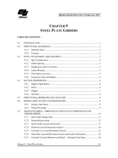
3 Key Terms Altimetry Lenker rod Automatic pendulum level Mean sea level Backsight (+shot) National Geodetic Vertical datum (NGVD 1929)Bench mark North American Vertical DatumCurvature (NAVD 1988) Datum Pegging a level Direct LEVELING Philadelphia rod differential LEVELING Plumb line Elevation Profile LEVELING Foresight (-shot) Reciprocal LEVELING Refraction Horizontal line Three-wire LEVELING Horizontal plane Trigonometric LEVELING Intermediate foresight (side shot) Turning point (TP) LEVELING Vertical difference Level surface Vertical line Level line 6-2 LEVELING Video Presentation Outline Basic Concepts Elevation Elevation Datum Level Lines Horizontal Line 2 1 Benchmark Vertical Lines Earth's Surface 90 Figure 6-1.
4 LEVELING concepts. Level line Horizontal line Vertical line Datum 6-3 Caltrans LS/LSIT Video Exam Preparation Course Curvature and Refraction Curvature, c Refraction, r Horizontal Line Line of Sight HI Elevation Distance Datum Vertical Line 90 to Horizontal Level Surface (c+r) Figure 6-2. Curvature and refraction. Curvature Refraction The formula for computing the combined effect of curvature and refraction is: C + R = C = correction for curvature R = correction for refraction K = sighting distance in thousands of feet Corrections for various distances Distance Correction 100' ' 200' ' 500' ' 700' ' 1 mile ' 6-4 8 Slope Distance (S) LEVELING Three Methods of Vertical Measurement LEVELING Direct Vertical Measurement LEVELING Altimetry Direct elevation rods Lasers Trigonometric LEVELING Equipment Method Calculation C Elev.
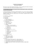
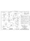
5 B = Elev. A + + (cos Z) (S) - rod - (c+r) Z H EHorizontal Line Rod (r)Elev. Vertical D B HI A Figure 6-3. Trigonometric LEVELING . 6-5 Caltrans LS/LSIT Video Exam Preparation Course differential LEVELING Equipment Method Calculations ' Foresight ' Backsight ' Graduated Rod Backsight Foresight ' TP-1 BM "A" Elevation ' Figure 6-4. differential LEVELING . Notekeeping for differential LEVELING Standard notekeeping + V Elev. ( ) #2 #1 Figure 6-5. Profile LEVELING noteform. 6-6 LEVELING Three-Wire LEVELING Method Foot Rod Figure 6-6. Level notes for foot rod from noteforms for surveying measurements. (Reproduced with permission from Landmark Enterprises.)
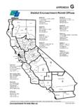
6 6-7 + .. _ , ~ , ,7 -~ 1,.~ '" . ~ "' - - "' <# .. !I, ~- .. ~ ; -~-" ' ' ~.d.. _ :f/1'.~~- . M ..,, d ~-~n .,.. ~ ,.. > . ,. ::; -" ~ --<- u: .. "" -~ IN ' ' ,.. , ' .. "'* "' , , '"' - .. , .. ~ .. u -,_. f-<'"'-J ~g .. 1""--' .. ' ' f<A---~ < , -~-> ~ . , -' . -j6 ;.-; .., ~ .. ~ S <l -~ , '' ~$ -""'"' I 0 - ,. -- .. , .., ~ .. --.) .. ' Caltrans LS/LSIT Video Exam Preparation Course Meter Rod Figure 6-7. Level notes for meter rod from noteforms. (Reproduced with permission from Landmark Enterprises.) 6-8 LEVELING Special LEVELING Procedures Figure 6-8.
7 Pegging a level. Error in Level 1 B A 100' 100' Sample Peg Test Station Backsight (+) Foresight Elevation A (assumed) B A B ' ' ' ' Adjustment = elevation of B from setup 1 - elevation of B from setup 2. 6-9 Caltrans LS/LSIT Video Exam Preparation Course Plus Rod Shot Plus Rod Shot BM 2 Setup 2 Setup 1 BM 1 Figure 6-9. Reciprocal LEVELING . 6-10 LEVELING Classification of Accuracy Standards and Adjustments General Specifications for Vertical Control Field Procedures Order Class First I First II Second I Second II Third Minimal Observation Method Micrometer Micrometer Micrometer or Three-Wire Center Wire Three-Wire Section Running DR, DS, or MDS DR, DS, or MDS DR DR DR Difference of forward and backward sight lengths never to exceed: per setup (m) 2 5 5 10 10 per section (m) 4 10 10 10 10 Maximum sight length (m) 50 60 60 70 90 Minumum ground clearance of line of sight (m) Even no.
8 Of setups when not using LEVELING rods with detailed calibration yes yes yes yes Determine temp. gradient for vert. range of line of sight for each setup yes yes yes Maximum section misclosure (mm) 3 D 4 D 6 D 8 D 12 D Maximum loop misclosure (mm) 4 E 5 E 6 E 8 E 12 E Single-Run Methods Reverse direction of single runs every half day yes yes yes Non-reversible compensator LEVELING instruments Off-level/relevel instrument bet. observing the high and low rod scales yes yes yes Three-Wire Method Reading check (difference between top and bottom intervals) for one setup not to exceed (tenths of rod units) 2 2 3 Read rod first in alternate setup method yes yes yes Double Scale Rods Low-high scale elevation difference for one setup not to exceed (mm) With reversible compensator Other instrument types: Half-centimeter rods Full-centimeter rods DS-Double Simultaneous procedure DR-Double-Run MDS-Modified Double Simultaneous D-shortest length of section (one-way) in km.
9 E-perimeter of loop in km. # Must double-run when using three-wire method * May single-run if line length between network control points is less than 25 km and may single-run if line length between network control points is less then 10 km. NOTE: See Geometric Geodetic Accuracy Standards and Specifications for Using GPS Relative Positioning Techniques, Federal Geodetic Control Committee for latest specifications. Figure 6-10. General Specifications for Vertical Control, National Geodetic Survey. 6-11 Caltrans LS/LSIT Video Exam Preparation Course Adjustments to Level Runs Length of lines methods Number of turning points method Least squares method Sample Test Questions 1.
10 When pegging a level the surveyor reads on the backsight rod and on the foresight rod. After moving the level adjacent to the backsight rod, a reading of is taken on the near rod. What should be on the far rod? 2. When pegging a level, how far apart should the rod readings be taken? 3. The effects eliminated by keeping backsights and foresights equal are _____ and _____. 4. Does an instrument in perfect adjustment sight a level line to a distant object? Explain. 5. Fill in the missing data in the sample differential level run below. Station (+) ( ) Elevation A 1 2 B e. a. d. b. (top Pipe) c. f. ( ) 6-12 LEVELING 6. What is the misclosure in the sample differential level run in problem 5?