Transcription of Lexus ES350 - Metra Online
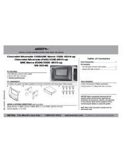
1 Installation instructions for part 99-8162G. Lexus ES350 (Non-NAV models only) 2007-2012 Table of Contents 99-8162G Dash Disassembly . Lexus ES350 Kit Kit Assembly KIT FEATURES . ISO DIN radio provision with 6. ISO DIN radio provision with pocket ISO Double DIN radio provision . ISO Double DIN radio 7. Painted to match factory finish TOOLS REQUIRED. KIT COMPONENTS Phillips screwdriver Panel removal tool A) Radio trim panel B) Brackets C) Pocket D) (8) #8 x 3/8 Phillips screws Torx driver A B C D. CAUTION: Metra recommends disconnecting the negative battery terminal before beginning any installation, unless the vehicle manufacturer recommends against so. Please check with your local Dealership for more information.
2 All accessories, switches, climate controls panels, and especially air bag indicator lights must be connected before reconnecting the battery or cycling the ignition. Also, do not remove the factory radio with the key in the on position, or the vehicle running. It would be best to remove the key from the ignition and then wait a few seconds WIRING & ANTENNA CONNECTIONS (sold separately). REV. 8/26/2015 INST99-8162G. before removing the factory radio. Wiring Harness: TYTO-01 Antenna Adapter: Not required Metra . The World's best kits. COPYRIGHT 2015 Metra ELECTRONICS CORPORATION. 99-8162G. Dash Disassembly 1. Unsnap and remove the shifter trim. (Figure A). 2. Unsnap and remove the vent assembly above the radio.
3 (Figure B). 3. Remove (2) screws above the radio in the vent cavity. (Figure C). 4. Remove the small side center console trim panels to expose and Driver side remove (2) 10 mm screws and remove radio. (Figures D, E, F, G) (Figure B) (Figure D) (Figure F). Continued on next page Passenger side (Figure A) (Figure C) (Figure E) (Figure G). 2. 99-8162G. Dash Disassembly 5. Remove the factory radio brackets. (Figure H). 6. Unsnap the radio chassis and controls from the climate control and side trim panels. (Figure I). 7. Remove (4) Philips screws to remove the climate control back plate. (Figure J). 8. Remove (4) outer corner Phillips screws from the climate control circuit board. (Figure K) (Figure H) (Figure J).
4 Continued on next page (Figure I) (Figure K). 3. 99-8162G. Dash Disassembly 9. Remove (2) Philips screws to separate the side trim panels from the climate control. (Figure L). 10. Unclip and remove the factory side trim panels. (Figure M). 11. Using a pick tool, remove the (2) temp switches from the side panels. (Figure N). 12. Modify the factory climate control, removing the side panel mounting tabs, as shown in the diagram. (Figure L) (Figure N). (Figure O). Continue to kit preparation Remove shaded area (Figure M) (Figure O). 4. 99-8162G. Kit Preparation 1. Snap the factory climate switches into the radio trim panel. (Figure A). 2. Mount the modified climate controls to the radio trim panel with the (4) screws previously removed.
5 (Figure B). Continue to kit assembly (Figure A) (Figure B). 5. 99-8162G. Kit Assembly ISO DIN radio provision with pocket 1. Connect the radio brackets to the radio housing trim panel with the (4) #8 x 3/8 Phillips screws supplied and use the factory screws to attach the brackets to the factory climate controls. (Figure A). 2. Mount the pocket to the bracket/. panel assembly with the (4) #8 x 3/8 . Phillips screws supplied. (Figure B). 3. Remove the metal DIN sleeve and trim ring from the aftermarket radio. 4. Slide the radio into the assembly and secure with screws supplied with the radio. (Figure C) (Figure A) (Figure B) (Figure C). 5. Locate the factory wiring harness and antenna plug in the dash and make all necessary connections to the radio.
6 Metra recommends using the proper mating adapters from Metra and/or AXXESS. 6. Mount the new radio assembly into the dash and reassemble the dash in reverse order of disassembly. 6. 99-8162G. Kit Assembly Double DIN radio provision 1. Connect the radio brackets to the radio housing trim panel with the (4) #8 x 3/8 Phillips screws supplied and use the factory screws to attach the brackets to the factory climate controls. (Figure A). 2. Slide the radio into the assembly and secure with screws supplied with the radio. (Figure B). 3. Locate the factory wiring harness and antenna plug in the dash and make all necessary connections to the radio. Metra recommends using the proper mating adapters from Metra and/or AXXESS.
7 (Figure A) (Figure B). 4. Mount the new radio assembly into the dash and reassemble the dash in reverse order of disassembly. 7. Installation instructions for part 99-8162G. IMPORTANT. If you are having difficulties with the installation of this product, please call our Tech Support line at 1-800-253-TECH. Before doing so, look over the instructions a second time, and make sure the installation was performed exactly as the instructions are stated. Please have the vehicle apart and ready to perform troubleshooting steps before calling. KNOWLEDGE IS POWER. Enhance your installation and fabrication skills by enrolling in the most recognized and respected mobile electronics school in our industry.
8 Log onto or call 800-354-6782 for more information and take steps toward a better tomorrow. Metra recommends MECP. certified technicians REV. 8/26/2015 INST99-8162G. Metra . The World's best kits. COPYRIGHT 2015 Metra ELECTRONICS CORPORATION. INSTRUCCIONES DE INSTALACI N PARA LA PIEZA 99-8162G. IMPORTANTE. Si tiene dificultades con la instalaci n de este producto, llame a nuestra l nea de soporte t cnico al 1-800-253-TECH. Antes de hacerlo, revise las instrucciones por segunda vez y aseg rese de que la instalaci n se haya realizado exactamente como se indica en las instrucciones. Por favor tenga el veh culo desarmado y listo para ejecutar los pasos de resoluci n de problemas antes de llamar.
9 K. EL. NOWLEDGE. Mejore sus IS P. CONOCIMIENTO ESOWER. PODER. habilidades de and instalaci n y fabricaci n Enhance your installation fabrication skills by inscribi ndose enrolling in the en la escuela most de dispositivos recognized electr nicos and respected REV. 8/26/2015 INST99-8162G. mobile m vileselectronics school m s reconocida in our industry. y respetada de nuestra industria. Log onto Reg strese or call en o llame al 800-354-6782 for more information and take steps 800-354-6782 para obtener m s informaci n y avance toward a better tomorrow. hacia un futuro mejor. Metra recomienda t cnicos con certificaci n del Programa de Certificaci n en Electr nica M vil (Mobile Electronics Certification Program, MECP).
10 Metra . The World's best kits. 1-800-221-0932 COPYRIGHT 2015 Metra ELECTRONICS CORPORATION. 99-8162G. Ensamble del kit Provisi n de radio doble DIN. 1. Conecte los soportes del radio al panel de la moldura de la carcasa del radio con los (4) tornillos Phillips #8 x 3/8 suministrados y use los tornillos de f brica para fijar los soportes a los controles de clima de f brica. (Figura A). 2. Deslice el radio en el ensamble y suj telo con los tornillos suministrados con el radio. (Figura B). 3. Localice el arn s de cableado de f brica y el conector de la antena en el tablero y haga todas las conexiones necesarias al radio. Metra recomienda que use adaptadores adecuados de (Figura A) (Figura B).