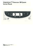
Transcription of LigaSure Vessel Sealing Generator
1 Service ManualLigaSure Vessel Sealing Generator iiLigaSure Vessel Sealing Generator Service ManualThis manual and the equipment it describes are for use only by qualified medical professionals trained in the particular technique and surgical procedure to be performed. It is intended as a guide for servicing the Valleylab LigaSure Vessel Sealing Generator only. Additional information about using the Generator is available in the LigaSure Vessel Sealing Generator User s covered in this manualValleylab LigaSure Vessel Sealing Generator - 120V / 240 VThe LigaSure Vessel Sealing Generator Service Manual consists of two parts the text and a Schematics Part Number 1009892 Effective Date May 2008 Trademark acknowledgmentsLigaSure and Instant Response are trademarks of Valleylab, Boulder, or more of the following patents and corresponding foreign patents cover the LigaSure Vessel Sealing Generator and accessories.
2 Additional patents byValleylab, a division of Tyco Healthcare Group LPBoulder, Colorado 80301-3299 USAE uropean RepresentativeTyco Healthcare UK , PO13 0AS, UKFor information call 1-800-255-8522 / 1-303-530-2300 Made in USA Printed in USA 2008 Valleylab All rights reserved. CautionFederal (USA) law restricts this device to sale by or on the order of a ,776,1306,228,0836,682,5285,599,3446,277 ,1176,685,7015,720,7446,398,7796,726,686 5,827,2716,402,7436,743,2296,033,3996,45 1,018D-424,6946,039,7336,464,704D-425,20 16,050,9966,458,130D-449,8866,068,6276,5 11,480D-457,9586,179,8346,585,735D-457,9 590086 LigaSure Vessel Sealing Generator Service ManualiiiPrefaceThe service manual describes the Valleylab LigaSure Vessel Sealing Generator .
3 Descriptions of the system, its functions, specifications, and theory of operation Step-by-step instructions on how to set up, calibrate, troubleshoot, and maintain the system Step-by-step instructions on how to replace specific components Parts lists and Used in this GuideWarningIndicates a potentially hazardous situation which, if not avoided, could result in death or serious a hazardous situation which, if not avoided, may result in minor or moderate a hazard which may result in product an operating tip or maintenance Vessel Sealing Generator Service ManualLigaSure Vessel Sealing Generator Service ManualvPreface iiiConventions Used in this Guide iiiChapter 1. Service Personnel SafetySafety Information 1-2 Warnings, Cautions, and Notices 1-2 General 1-2 Active Accessories 1-3 Fire/Explosion Hazards 1-3 Electric Shock Hazards 1-3 Servicing 1-4 Calibration 1-5 Cleaning 1-5 Chapter 2.
4 IntroductionGeneral Description 2-2 Vessel Sealing 2-2 Bipolar Operation 2-3 Instant Response Technology 2-3 Chapter 3. Controls, Indicators, and ReceptaclesList of Components 3-2 Front Panel 3-3 Features 3-4 Symbols 3-4 Vessel Sealing Controls and Indicators 3-5 Vessel Sealing Handset Receptacle (purple) 3-6 Bipolar Controls and Indicators 3-6 Bipolar Handset Receptacle (blue) 3-7 Rear Panel 3-8 Vessel Sealing Footswitch Receptacle (purple) 3-9 Bipolar Footswitch Receptacle (blue) 3-9 Option Panel 3-10 Chapter 4. Technical SpecificationsPerformance Characteristics 4-2 General 4-2 Dimensions and Weight 4-2 Operating Parameters 4-2 Transport and Storage 4-3 Duty Cycle 4-3 Internal Memory 4-3 Audio Volume 4-3 Serial Port 4-4RF Activation Port 4-5 Expansion Port 4-5viLigaSure Vessel Sealing Generator Service ManualLow Frequency (50-60 Hz) Leakage Current (AAMI HF-18-1993) 4-6 High Frequency (RF) Leakage Current (IEC 60601-2-2) 4-6 Input Power 4-7 Power Cord Specification 4-7 Standards and IEC Classifications 4-8 Class I equipment (IEC 60601-1) 4-8 Type CF equipment (IEC 60601-1)
5 /Defibrillator Proof 4-9 Liquid Spillage (IEC 60601-2-2, clause ) 4-9 Static Electricity Discharge Interference (IEC 60601-1-2 and IEC 61000-4-2) 4-9 Electromagnetic Interference 4-9 Electromagnetic Compatibility (IEC 60601-1-2 andIEC 60601-2-2) 4-9 Voltage Transients (Emergency Generator Mains Transfer) 4-10 Output Characteristics 4-14 Maximum Generator Output 4-14 Output Waveform 4-15 Output Power vs. Impedance Graphs 4-17 Chapter 5. Principles of OperationBlock Diagram 5-2 Functional Overview 5-3 Vessel Sealing 5-3 Bipolar Operation 5-3 Instant Response Technology 5-3 Control Board 5-4 Microcontrollers 5-4 Feedback Microcontroller 5-5 Feedback Microcontroller Memory 5-5 Shared RAM 5-6I/0 Expansion 5-6 Keyboard Interface and Activation Inputs 5-6 Power Supply Supervisor Circuit 5-6A/D and D/A Conversion 5-7 Waveform Generation (T_ON)
6 5-7T_ON Average Check 5-7 Audio Alarm 5-8 Serial Interface 5-8 Dosage Error Algorithm 5-8 Instant Response Algorithm 5-9 Front Panel 5-10 Membrane Keyboard 5-10 Power Switch 5-10 Display Board 5-10RF Indicator Lamps 5-10 LED and Seven-Segment Display Drivers 5-11 LigaSure Vessel Sealing Generator Service ManualviiRegrasp Display 5-12 Mode Select and Power Control Switches 5-12 Footswitch Board 5-13 Footswitch Decode Circuit 5-13 Audio Circuit 5-14 High Voltage (HV) Power Supply Board 5-15 Power Entry Circuit 5-15 Auto Mains Switching Circuitry 5-15AC/DC Converter 5-15DC/DC Switching Regulator 5-16 Thermal Sensing (High Temperature Limit) 5-17 Low Voltage Power Supply 5-17RF Board 5-18 Operative Modes 5-19RF Driver 5-20RF Output 5-20RF Output Relays 5-21 EKG Output Relay 5-21 Primary Sense Circuits 5-22 Redundant Sense Circuits 5-23 Single Fault Protection Circuit 5-24 Heat Sink 5-25 IsoBloc Circuit 5-25 Integration Functions 5-26 Smart Connector Boards 5-28 Chapter 6.
7 Setup, Tests, and AdjustmentsSetting Up the Generator 6-2 Connecting Bipolar or Macrobipolar Accessories 6-3 Setting the Output for the Selected Mode 6-4 Activating the Surgical Instrument 6-4 Periodic Safety Check 6-5 Recommended Test equipment 6-5 Inspecting the Generator and Accessories 6-6 equipment 6-6 Procedure 6-6 Inspecting Internal Components 6-8 equipment 6-8 Procedure 6-8 Using the RS-232 Serial Port 6-9 equipment 6-9 Disconnect the Computer from the Generator 6-11 Testing the Generator 6-11 Confirming Outputs 6-11 Checking the Vessel Sealing Output 6-12 Checking the Bipolar Output 6-12viiiLigaSure Vessel Sealing Generator
8 Service ManualChecking Low Frequency Leakage Current and Ground Resistance 6-13 Checking High Frequency Leakage Current and Ground Resistance 6-14 Calibrating the LigaSure Generator 6-16 Preparing for Calibration 6-17 Chapter 7. TroubleshootingInspecting the Generator 7-2 Inspecting Receptacles 7-2 Inspecting Internal Components 7-4 Correcting Malfunctions 7-5 Responding to System Alarms 7-10 Chapter 8. Replacement ProceduresSafety 8-2 Map of Major Components 8-3 Cover 8-4 Tools Needed 8-4 Remove the Cover 8-4Re-install the Cover 8-5 High Voltage (HV) Power Supply Board 8-5 Tools Needed 8-5 Remove the High Voltage Power Supply Board 8-5 Install a New HV Power Supply Board 8-7 Control Board and Battery 8-9 Tools Needed 8-9 Remove the Control Board 8-9 Replacing the Battery 8-11 Tools Needed 8-11 Procedure 8-11 Install the Control Board 8-12 Footswitch Board 8-13 Tools Needed 8-13 Remove the Footswitch Board 8-13 Install a New Footswitch Board 8-13 Low Voltage (LV)
9 Power Supply Board 8-15 Tools Needed 8-15 Remove the Low Voltage (LV) Power Supply Board 8-15 Install a New LV power supply board 8-16 Front Panel and Display Board 8-17 Tools Needed 8-17 Remove the front panel 8-17 Remove the Display Board 8-19 Install the Display Board 8-20 Install the Front Panel 8-20 Power Switch 8-22 Tools Needed 8-22 LigaSure Vessel Sealing Generator Service ManualixRemove the Power Switch 8-22 Install a New Power Switch 8-24RF Board and Heat Sink 8-25 Tools Needed 8-25 Remove the RF board 8-25 Remove the Heat Sink 8-28 Install the Heat Sink 8-28 Install the RF Board 8-29 Power Entry Module 8-30 Tools Needed 8-30 Remove the Power Entry Module 8-30 Install the
10 Power Entry Module 8-31 Fuses 8-32 Tools Needed 8-32 Two Fuses in the Fuse Drawer 8-32 Three Fuses on the RF Board 8-33 One Fuse on the HV Power Supply Board 8-33 Chapter 9. Repair PolicyResponsibility of the Manufacturer 9-2 Returning the Generator for Service 9-2 Returning Circuit Boards 9-4 Service Centers 9-4 Chapter 10. Service PartsOrdering Replacement Parts 10-2 Map of Major Components 10-2 List of Parts 10-3 Assembly, Box 10-3 Generator Assemblies 10-4 Front Panel Assembly 10-5 High Voltage Power Supply Board Assembly 10-6RF Board Assembly 10-7 Control Board Assembly 10-8 Chapter 11. WarrantyxLigaSure Vessel Sealing Generator Service ManualCHAPTER 1 LigaSure Vessel Sealing Generator Service Manual1-11 Service Personnel SafetyValleylab stresses safety in the use and servicing of its electrosurgical equipment .