Transcription of Line to Ground Voltage Monitoring on …
1 Line to Ground Voltage Monitoring on ungrounded and impedance grounded power Systems December 2010/AT301. by Reza Tajali, Square D power Systems Engineering Make the most of your energy SM. Revision #1 12/10. Abstract power Monitoring devices are sometimes used on ungrounded and impedance grounded systems to record and alarm on line to Ground voltages. This recorded line to Ground Voltage data can be manipulated using a host of data analysis tools to evaluate insulation stress on power system components . However, ungrounded and impedance grounded systems have specific issues that impact proper application of metering equipment. Get connected Voltage transformers are especially prone to misapplication. This paper is intended to provide a road map for to power proper application of power Monitoring in these circuits. The subject of grounding is explored to demonstrate the basic issues with ungrounded systems.
2 A discussion of metering principles is provided to identify the limitations for this type of metering. Ample discussion is provided on the subject of controlling ferro-resonance. I. Introduction power monitors are generally designed for two basic metering connections. Three element metering is normally used on 3 4w feeders where system neutral is available. These systems are solidly grounded . Two element metering is generally applied to any 3 3w feeder. A 3 3w feeder is one for which system neutral is not available or can not be used. Specifically this includes ungrounded Delta, ungrounded wye and impedance grounded wye systems. See Figure 1. The special application discussed in this paper utilizes three element metering on an ungrounded or impedance grounded system. This is a variation from the norm in metering electricity. This method of metering is applied to measure line to Ground voltages.
3 Line to Ground Voltage Monitoring on ungrounded and impedance grounded power Systems II. Metering Accuracy The principle behind all electricity meters, most popularly known as Blondel theorem, is stated as follows: The total power of a general n-phase system is the sum of n powers. These powers are given by n currents which issue from the n terminals, with the n potential differences of these terminals against any arbitrary Get connected terminal.. to power For a three phase system this principle is shown graphically in Figure 2. The reference point for voltages (Vx). can be any point. In the case of the metering system discussed in this paper, this point is taken to be the earth potential. This point does not have to be the neutral of the system. With voltages measured line to Ground in an ungrounded or impedance grounded system, the individual phase power values (KW, KVAR, KVA) may be meaningless.
4 Some of these individual phase powers may come out positive, some may come out negative. But, per Blondel's theorem, the total 3 phase power will always add up to the correct value. Additionally, if the meter calculates power factor by dividing 3 phase power with 3 phase KVA, the power factor values will be correct. If the meter displays any individual phase power factor values, those values will be meaningless. There is not one consistent method for calculating the power factor especially in the presence of current and Voltage distortion. Different power monitors use different methods. Individual manufacturer must be consulted. Disturbance Monitoring is an important feature of power monitors which will be affected by the connection method. With the three element connection discussed in this paper, disturbances (sag, swell, transients) are measured with respect to Ground . Voltage distortion is also measured with respect to Ground .
5 Care must be exercised when interpreting these data. Vc Ic Va Ia Vx Ib Vb Figure 2: Blondel theorem III. What to Measure The following values are of particular interest on ungrounded systems: 1.) RMS value of line to Ground voltages: A significant increase in Voltage unbalance will signify a Ground fault condition. 2.) Line to Ground Voltage transients: If the system is ungrounded , be prepared to see a great number of transients on some feeders especially on an aging power system. These transients may disrupt sensitive electronic equipment and stress the insulation on electrical machinery. Waveform captures from these transients can be used to evaluate possibility of partial (arcing) Ground faults and ferro-resonance. AT301 | 3. Line to Ground Voltage Monitoring on ungrounded and impedance grounded power Systems IV. impedance grounded Systems Figure 3 depicts the Voltage connection used for Monitoring line to Ground voltages on an impedance grounded systems.
6 By Monitoring line to Ground voltages it is possible to detect and alarm in case of Ground faults. Get connected In addition to individual phase currents, the power monitor will measure and display the vector sum of the to power phase currents. With the connection under discussion, this vector sum will be equal to the Ground current. Some power monitors have the capability to directly measure the Ground current. See Figure 4. Even though the Voltage transformers are connected line to Ground , it is recommended that the transformers'. primary side have a Voltage rating at least equal to the system's line to line Voltage . This is because a line to Ground fault on any phase will impress the line to line Voltage on the transformers on the other two phases. This type of system is not prone to Voltage transformer ferro-resonance. Therefore, the metering circuit will not require any burdening resistors (the subject of ferro-resonance will be discussed later in this paper.)
7 Figure 3: Optional Voltage connection for impedance grounded systems. AT301 | 4. Line to Ground Voltage Monitoring on ungrounded and impedance grounded power Systems Get connected to power Figure 4: Current transformer connections for impedance grounded system V. ungrounded Systems A. ungrounded Systems' Inherent Instability Historically, there has been a gradual trend in American practice from ungrounded systems to solidly grounded or impedance grounded systems. Initially, most systems were ungrounded - this was the natural thing to do as the Ground connection was not necessary for the actual transfer of power . This method had a strong argument in it's favor as insulation failure on one of the phases could be tolerated for some time until the fault could be located and repaired. A major limitation to the ungrounded system has been the arcing Ground fault. By arcing Ground is meant a process by which alternate clearing and re-striking of the arc causes recurring high surge voltages.
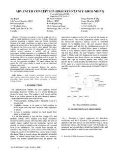
8 These surge voltages stress the insulation on other parts of the system causing premature equipment failure. Additionally, in an ungrounded system, the voltages to Ground are inherently unstable. To understand these principles a simplified model of the system is drawn (Figure 5). AT301 | 5. Line to Ground Voltage Monitoring on ungrounded and impedance grounded power Systems c Ic a Ia b Ib Co Get connected to power c Ia Ic a Ib b Figure 5 Simple ungrounded system The system capacitance to Ground is modeled by three shunt capacitors C . Under ideal conditions, with system impedances balanced, the charging currents from the three capacitors add to zero. So far as voltages are concerned, a virtual neutral point can be envisioned in the delta transformer which will be at Ground potential in such an ideal system. In actual practice the system impedances are not exactly balanced and the virtual neutral point, discussed above, is not at earth potential.
9 Therefore, the individual phase voltages to Ground will not be equal. Figure 6 illustrates the situation encountered in a line to Ground fault. During an arcing Ground fault the circuit depicted in Figure 6 is opened and re-struck due to the action of the arcing fault. This action creates significant Voltage transients. c a b 0 IF. Co G. c Vcg IF. Igb Igc G. b Vbg Figure 6 Ground fault on simple ungrounded system AT301 | 6. The solution to these problems of ungrounded systems is to provide system grounding, either directly or through an impedance . In case of a wye connected system the neutral point is directly available and can be used. In case of a delta connected system, the neutral point can be derived through grounding transformers. Figure 7 demonstrates two approaches in using grounding transformers. The grounding resistance is sized so that the magnitude of Ground current during a line to Ground fault would Get connected be slightly larger than the system capacitive charging current.
10 This provides the highest value of resistance that to power is acceptable (hence High Resistance Ground ). The grounding resistance can be smaller than this value. But at these lower values the magnitude of Ground fault current increases. Such properly sized grounding resistance will provide damping to Voltage transients during arcing Ground faults. It can be said that it stabilizes the power distribution system. Essentially, this kind of system has all the advantages of ungrounded systems plus the added benefit of controlling line to Ground Voltage transients and Voltage transformer ferro-resonance (Ferro-resonance will be discussed later in this paper). Once the magnitude of the Ground fault current is established, the transformers in Figure 7 are sized to carry this current. This establishes the thermal rating of the transformers. Figure 3: Ground Fault on Load Bus #1 Could Shut Down the Entire Data Center B.