Transcription of ADVANCED CONCEPTS IN HIGH RESISTANCE …
1 ADVANCED CONCEPTS IN high RESISTANCE GROUNDING Copyright Material IEEE Paper No. PCIC-2012-25 Ajit Bapat Life Senior Member, IEEE Power Solutions 257 Burbank Drive North York, On M2K 2S4 Canada Dr. Robert Hanna Fellow , IEEE RPM Engineering 2816 Hammond Road Mississauga, On, L5K 2R1 Canada Sergio Panetta, Senior Member, IEEE I-Gard Corp. 1-7615 Kimbel St Mississauga, On L5S 1A8 Canada 1 Abstract - RESISTANCE grounding is relatively simple and easy to apply in radial distribution systems at Low voltage .
2 When high RESISTANCE grounding is applied, using one Neutral Grounding Resistor at the supply transformer, an alarm system to detect and indicate the ground fault is then required by the installation codes. This practice has been in use and is widely applied. This paper explores the application when the distribution systems involve multiple sources operating in parallel, such as multiple transformers, multiple generators or a combination. The sizing of NGR is explored and application of hybrid grounding is suggested for situations where Low RESISTANCE grounding needs to be used.
3 In medium voltage systems 15 kV to 36 kV the practice has been to use very low RESISTANCE grounding. The paper suggests that the criteria for NGR sizing should be based on the net distributed charging current only. Application examples are presented showing the selective instantaneous feeder tripping and concept of hybrid grounding in Low and Medium voltage systems Index Terms high RESISTANCE grounding, selective second fault tripping, multi-circuit ground fault relay, hybrid generator grounding, stator ground fault, hybrid grounding in Medium voltage Systems.
4 I. INTRODUCTION The petrochemical Industry has been applying Neutral Grounding Resistors (NGRs) on it s power distribution system for many years. The concept is well known and has been in use as best practice in the petro chemical Industry. This has been driven by three basic factors: 1) Power continuity, nothing needs to trip in the event of a ground fault. 2) Negligible damage at the point of fault resulting in lower repair costs and faster return of faulty equipment to service.
5 3) In case of accidents, minimal arc flash hazard from phase to ground fault. It is the best practice to have the low voltage (LV) and medium voltage (MV) applied with high RESISTANCE Grounding (HRG) [1],[2]. This has often taken the form of simple resistor applied between transformer neutral and ground . An alarm is raised on the occurrence of a ground fault in the distribution. The current flows through the resistor or the voltage rise of the neutral or the reduction of voltage to ground on the faulted phase can be used to initiate this alarm.
6 Phase to ground voltage also identifies the faulted phase. To indicate which feeder has a fault, zero sequence sensors with sensitive ground fault relays are applied. The alarm level is usually set for 50%, or less of the resistor let through current. This avoids sympathetic alarms caused by the unbalanced capacitive leakage current in unfaulted feeders [3]. In modern relays the zero sequence sensor signal causes a pick up then the simultaneous presence of unbalanced voltage is verified before alarm is indicated.
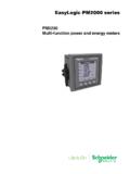
7 Often to avoid nuisance alarms caused by inrush currents and non linear loads, the Zero Sequence Current Sensor output is filtered and only fundamental signal is extracted. These measures have been effective in avoiding nuisance alarms and trips in sensitive ground fault relays. This practice has been well accepted and understood. The purpose of this paper is to explore RESISTANCE grounding applications and offer suggestions for enhancements for both LV and MV Systems. Fig. 1 Typical Delta/Delta installation II.
8 high RESISTANCE GROUNDING Fig. 1 illustrates a typical application for delta/delta transformer with 480 V secondary. The grounding resistor is applied on the line side of the main breaker using a zigzag transformer and a 2A let through resistor. All the feeders are monitored and ground alarm identifying faulted feeder and phase is provided by a multi-circuit ground fault relay A. Benefits of high RESISTANCE Grounding 600 A600 A600 A600 A3000 A4160 V480 VPulsing ResistorAlarmDi ageSense480 V. BUS Multi CircuitGF Re l a y 2 1.
9 Arc Flash and Blast hazard for a line to ground fault is prevented. For systems up to 4160 V where the resistor let through current is 10 A or less, the arc blast is unlikely. Such systems can continue to operate with one ground fault. Fault does not escalate and so the distribution system is safer. Accidents causing Line to ground faults will not produce hazardous blast or arc flash [4]. 2. Fault Damage at the point of fault is very low and can be easily repaired. It minimizes maintenance repair costs.
10 This is a significant advantage for protection of machines. Motor and generator laminations will not get burnt and winding repair costs will be small [4]. 3. The small current is safely carried continuously by the bonding path without causing harmful step and touch potential rise. 4. For systems up to 4160 V where the resistor let through current is 10 A or less, the line to ground fault can be kept on the system continuously. No fault isolation needs to occur per CEC 10-1100 through 1108 [5], and NEC , and [6].