Transcription of Liquid Level Switch liquiphant M FTL 50, 51, 50 H, …
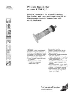
1 TechnicalInformationTI 328F/24/aeLiquid Level Switchliquiphant M FTL 50, 51, 50 H, 51 HLevel limit Switch for all liquidsSuitable for use in hazardous areas, chemicals,food and pharmaceuticalsFeatures and Benefits Large selection of processconnections: universal use Installs in threaded openings assmall as 3/4 or in flanges as smallas 1 Wide variety of electronics, relay, 4 to 20 mA Switch ,NAMUR, PFM signal output,transistor: the right connection forevery process control system No calibration: quick, low-coststart-up No mechanical moving parts: nomaintenance, no wear, economicallong operating life Monitoring of fork for damage:guaranteed operationApplicationsThe liquiphant M is a Level limit switchfor use in all liquids With temperatures between -40 and+ 300 F (-40 to + 150 C) Pressures up to 930 psig (64 bar) Viscosity up to 10,000 cP Density from SGUThe function is not affected by flow,turbulence, bubbles, foam, vibration, bulksolids content or build-up.
2 TheLiquiphant M is thus the ideal replace-ment for float switches, gap switches,capacitance and other Selection FTL 50: compact design, ideal formounting in pipes FTL 51: extension tube for up to115 inches maximum (3 m) FTL 50 H, FTL 51 H: with polishedfork and easy to clean processconnections and housings for foodand pharmaceutical applicationsHigh corrosion-resistant Alloy C4 isavailable for the fork and processconnections for applications in veryaggressive liquiphant M includes versions foruse in hazardous areas, includingintrinsically safe and M FTL 51with AluminumHousingand Extension Tube,ANSI Flange Mounted(Explosion Proof) liquiphant M FTL 50with PolyesterHousingand 3/4 NPTT hreadedConnectionLiquiphant M FTL 50 H withSS Housing and Tri-clamp The Power of Know HowFTL 50/51 50H/51 HEndress+Hauser2 The introduction of the liquiphant M, a new generation frequency shift tuning fork,brings greater application flexibility and reliability to Level Switch users.
3 Level swtichesare used in almost every processing and manufacturing facility around the mechanical devices (such as floats and displacers) are used in such applica-tions as spillage prevention, dry pump indication, and batch Level types of Level switches require high maintenance and process shutdowns dueto sticky, viscous fluids, gas bubbles or turbulence. The liquiphant M is not affectedby turbulence, bubbles, foam, vibration, build-up, high viscosity, or bulk solids liquiphant M uses frequency shift technology for limit detection. The forksvibrate at their resonant frequency. This frequency changes when covered oruncovered by the Liquid material, causing a change in the frequency which activates alimit liquiphant M provides continuous self-monitoring. The frequency shift of thetuning fork is monitored, an alarm state is indicated if there is fork corrosion ordamage. Loss of power and piezo drive failure are also liquiphant M can be mounted at any orientation and in pipe lines.
4 In applicationswhere room allows, the unit can be extended into the vessel (up to 115 ) with anextension or maximum limit detection in pipes or tanks containing all types of liquids ispossible with the liquiphant M, including hazardous areas, food and increasing requirements for overfill or spill detection of chemicals, wastes, andmany commodity fluids are ideal applications for the liquiphant M. The high reliabilityand low maintenance provides safety for owners of storage tanks, chemical tanks,and petroleum product storage; on land, tank cars and and system designRail car overspill protectionInternal support forextended 50/51 50H/51 HEndress+Hauser3 SystemA complete system consists of an electronic insert, housing, process connection on the application, the liquiphant M is available in various electronic andmechanical versions to fulfill industrial 51, 52, 54 FEL 55, 56, 57, 58 Level Signal OutputLiquiphant M FTLwith electronic insertsFEL 55, FEL 56, FEL 57, 58for connecting to aseparate switching unitor isolation amplifierLevel Limit Switch OutputLiquiphant M FTLwith electronic insertsFEL 51, FEL 52, FEL AreaSafe PLCI solationModular DesignPlug-in electronicinserts to mount inthe housingHousingsProcessConnectionsSensors FEL 51: Two-wire AC connectionFEL 52: Three-wire DC connection, PNPFEL 54: Universal power (AC / DC), DPDT relayFEL 55: Output 8 / 16 mA for remote switching unitFEL 56.
5 Output to / to mA for remoteswitching unit (NAMUR)FEL 57: Output 50 / 150 Hz, PFM, for remote switchingunit (Nivotester)FEL 58: Output to / to mA for remote switchingunit (NAMUR)Polyester " or 1" NPTANSI B , "(240 grit polishedavailable)Extended tube,maximum 115"(240 grit polishedavailable)1" Flush mountfor weld adapter(EE2)ANSI RF flangesfrom 1"1-1/2" / 2"Tri-clampor 2" Varivent304 SS SanitaryAluminum (alsofor hazardous)SpacersTemperaturespacers2nd line of defense,pressure-tightbushingNOTE: for coated sensors in aggressivechemical applications, refer to liquiphant MFTL 51 C, document TI 347F/24 50/51 50H/51 HEndress+Hauser4 Process Connection "( ) "( ) "( ) "( ) "(68) "( )32 "( )41 "( ) "(69)Threaded3/4" NPTANSI B psi300 F930 psi300 F300 FSee ratedpressure offlange145 psi248 F580 psi212 For360 psi300 F145 psi248 FANSI B B 2852E+H Partnumber52001047(page 15)Clampring andO-ring,installedon siteSealaccordingto design,installed onsiteClampring andfront sealinstalledon siteFork canbepositioned,refer toaccessories1" NPTGM2GM5GF2GF5 Axx(seeordercodes)TC2TE2EE2 Backing nut(supplied with unit)WE21-1/2"2"1" 2-1/2"Flange1" up to 4"Class 150 upto Class 600,raised faceTri-clamp Varivent Flush-mountedfor1"weldadapterConnectionC onstructionVersionStandardNotesMaximumPr essure/TemperatureCodeFTL 50/51 50H/51 HEndress+Hauser5 MinMax12> > N U~19 to 253 VAC50/60 HzI max.
6 350mAElectronic insert functionElectronic inserts for Level limitswitches FEL 51: two-wire AC version, Switch the load directly into the power supply circuitvia the thyristor FEL 52: three-wire DC version, Switch the load via the transistor (PNP) andseparate connection (preferably used with PLC controller) FEL 54: universal AC / DC version with DPDT relay, Switch the loads via two dry(potential-free) relay contacts FEL 55: two-wire loop-powered for separate switching unit for connecting to aPLC, signal transmission 16 / 8 mA (high to low current) along two-wire cabling FEL 56: two-wire for separate switching unit, signal transmission to / mA (low to high current) to EN 50227 (NAMUR) along two-wire cabling FEL 58: two-wire for separate switching unit, signal transmission to / mA (high to low current) to EN 50227 (NAMUR) along two-wire of connecting cable and other devices by pressing a push button on theelectronic insert.
7 FEL 57: two-wire for separate switching unit, PFM signal transmission, currentpulses superimposed on the power supply along the two-wire cabling. Testingat the switching unit without changing 51, 52:Between sensor and power supplyFEL 54:Between sensor, power supply and loadFEL 55, 56, 57, and 58:Refer to remote switching unit connectedElectronic insert wiring terminals, maximum 14 AWG ( mm2), stranded in cablesleeve according to DIN connection in housing, maximum 14 AWG ( mm2)External housing ground for plant grounding system, maximum 11 AWG (4 mm2)Electronic inserts for Level sensorsGalvanic isolationConnecting cablesElectronic insert operation and setupFEL 51, 52, 54 and 55: 2 switches for fail-safe mode and density change, green LEDto indicate power on, red LED to indicate switching status (flashes when sensor isdamaged by corrosion or when the electronics are defective)FEL 56.
8 2 switches for fail-safe mode and density change, green LED flashes toindicate power on, red LED indicates switching status (flashes when sensor isdamaged by corrosion or when the electronics are defective)FEL 57: 2 switches for density change and cyclical checking, green LED indicatespower is on, yellow LED indicates forks are covered (flashes when sensor is dam-aged by corrosion or when the electronics are defective)FEL 58: 2 switches for fail-safe mode and density change, green LED flashes rapidlyto indicate power on, flashes slowly on damage by corrosion on sensor or when theelectronics are defective, yellow LED indicates relay status. Test push button breakssensor circuit (refer to page 9).Display and operation elementsFTL 50/51 50H/51 HEndress+HauserFailsafe modeDependent on electronic insert specified, refer to pages 7 thru 11 Switch status for minimum / maximum residual current safety on electronic insert (withFEL 57 connected to remote switching unit FTL 325 P only).
9 Maximum fail-safe: the output switches to the power failure mode when fork iscovered (for use with overspill protection, etc.)Minimum fail-safe: the output switches to the power failure mode when fork isuncovered (for use with dry pump protection, etc.)Approximately seconds when forks are covered, approximately seconds whenforks are uncoveredWhen switching power on, the output assumes the alarm signal mode. After amaximum 2 seconds, it assumes the correct Switch status (exception, FEL 57).OutputOutput signalResponse timePower up responsePerformance characteristicsAmbient temperature, 73 F (23 C)Product temperature 73 F (23 C).Product density, 1 SGU (water)Viscosity, 1cPPressure, 0 psigSensor mounted vertically from topDensity selector Switch > by mounting position, maximum (1 mm) ( mm)Approximately (2 mm)Maximum + to (-40 to +300 F); maximum + mm to mm (-40 to+150 C)Maximum to ( to mm) at SGU to SGUM aximum 0 to at 0 to 870 psig; 0 to mm (0 to 60 bar gage)Reference conditionsMeasured errorRepeatabilityHysteresisEffects of product temperatureEffects of densityEffects of "(13 mm)Switchpointfor referenceconditions6 FTL 50/51 50H/51 HEndress+HauserWiring and Output FunctionL1 ExternalloadMaximum 253 VAC50/60 Hz1NN(GND) VACFEL < signalLEDsgreenred< : Unit must be connected inseries with a load.
10 Input power, 19 to 253 VAC, currentconsumption, mA Minimum voltage drop across theload at the electronic insert is 19 V *. When a relay cannot de-energizewith a residual current below mA,a resistor should be connected inparallel to the relay. Signal on alarm, < mA on powerfailure or damaged sensor Diagnostic warning, the red LEDflashes when sensor is damagedby corrosion, or when self-diagnostics detect electronics aredefective. Connectable load: load is switcheddirectly into the power supply circuitvia current (40 ms), A, max. 375 VA at 253 VAC ormax. 36 VA at 24 VAC (not short-circuit protected).Continuous max. 89 VA at253 VAC, max. VA at 24 VA at 253 V (10 mA),min. VA at 24 V (20 mA)* The terminal voltage at the electronicinsert must not be below 19 V. Note thevoltage drop across the electronic insert inthe conducting state (max. 19 V), theresidual current in the blocked state ( mA) and, when using low voltages, thevoltage drop across the load can be an indicator light orremote relay.