Transcription of LNK302/304-306 LinkSwitch-TN Family - Power
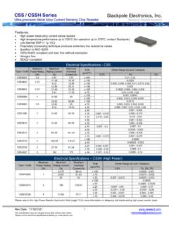
1 LNK302/304-306 . LinkSwitch-TN .. Family Lowest Component Count, Energy-Efficient Off-Line Switcher IC. Product Highlights Cost Effective Linear/Cap Dropper Replacement Lowest cost and component count buck converter solution FB BP. Fully integrated auto-restart for short-circuit and open loop + D S +. fault protection saves external component costs Wide Range LinkSwitch-TN DC. High-Voltage Output LNK302 uses a simplified controller without auto-restart for DC Input very low system cost 66 kHz operation with accurate current limit allows low cost PI-3492-041509. off-the-shelf 1 mH inductor for up to 120 mA output current Figure 1.
2 Typical Buck Converter Application (See Application Examples Section Tight tolerances and negligible temperature variation for Other Circuit Configurations). High breakdown voltage of 700 V provides excellent input surge withstand Frequency jittering dramatically reduces EMI (~10 dB). Minimizes EMI filter cost High thermal shutdown temperature (+135 C minimum). Much Higher Performance Over Discrete Buck and Passive Solutions Output Current Table1. Supports buck, buck-boost and flyback topologies 230 VAC 15% 85-265 VAC. Product4. System level thermal overload, output short-circuit and open MDCM2 CCM3 MDCM2 CCM3.
3 Control loop protection LNK302P/G/D 63 mA 80 mA 63 mA 80 mA. Excellent line and load regulation even with typical configuration LNK304P/G/D 120 mA 170 mA 120 mA 170 mA. High bandwidth provides fast turn-on with no overshoot Current limit operation rejects line ripple LNK305P/G/D 175 mA 280 mA 175 mA 280 mA. Universal input voltage range (85 VAC to 265 VAC) LNK306P/G/D 225 mA 360 mA 225 mA 360 mA. Built-in current limit and hysteretic thermal protection Table 1. Output Current Table. Higher efficiency than passive solutions Notes: Higher Power factor than capacitor-fed solutions 1.
4 Typical output current in a non-isolated buck converter. Output Power capability Entirely manufacturable in SMD depends on respective output voltage. See Key Applications Considerations Section for complete description of assumptions, including fully discontinuous conduction mode (DCM) operation. EcoSmart Extremely Energy Efficient 2. Mostly discontinuous conduction mode. Consumes typically only 50/80 mW in self-powered buck 3. Continuous conduction mode. topology at 115/230 VAC input with no-load (opto feedback) 4. Packages: P: DIP-8B, G: SMD-8B, D: SO-8C. Consumes typically only 7/12 mW in flyback topology with external bias at 115/230 VAC input with no-load Meets California Energy Commission (CEC), Energy Star, and EU requirements Applications Appliances and timers LED drivers and industrial controls and thermal shutdown circuitry onto a monolithic IC.
5 The start-up and operating Power are derived directly from the voltage on the Description DRAIN pin, eliminating the need for a bias supply and associated circuitry in buck or flyback converters. The fully integrated LinkSwitch-TN is specifically designed to replace all linear and auto-restart circuit in the LNK304-306 safely limits output Power capacitor-fed (cap dropper) non-isolated Power supplies in the during fault conditions such as short-circuit or open loop, under 360 mA output current range at equal system cost while reducing component count and system-level load protection offering much higher performance and energy efficiency.
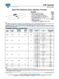
6 Cost. A local supply provided by the IC allows use of a non- LinkSwitch-TN devices integrate a 700 V Power MOSFET, safety graded optocoupler acting as a level shifter to further oscillator, simple On/Off control scheme, a high-voltage switched enhance line and load regulation performance in buck and current source, frequency jittering, cycle-by-cycle current limit buck-boost converters, if required. June 2013. This Product is Covered by Patents and/or Pending Patent Applications. LNK302/304-306 . BYPASS DRAIN. (BP) (D). REGULATOR. V. BYPASS PIN. UNDERVOLTAGE. +. V - V CURRENT LIMIT.
7 COMPARATOR. +. V. - VI. LIMIT. JITTER. CLOCK. DCMAX. FEEDBACK THERMAL. (FB) SHUTDOWN. OSCILLATOR. V -VT. S Q. R Q. LEADING. EDGE. BLANKING SOURCE. (S). PI-3904-032213. Figure 2a. Functional Block Diagram (LNK302). BYPASS DRAIN. (BP) (D). REGULATOR. V. FAULT. PRESENT. AUTO- RESTART BYPASS PIN. V COUNTER UNDERVOLTAGE. +. CLOCK. V - CURRENT LIMIT. RESET V COMPARATOR. +. - VI. LIMIT. JITTER. CLOCK. DCMAX. FEEDBACK THERMAL. SHUTDOWN. (FB) OSCILLATOR. V -VT. S Q. R Q. LEADING. EDGE. BLANKING SOURCE. (S). PI-2367-032213. Figure 2b. Functional Block Diagram (LNK304-306). 2. Rev. J 06/13 LNK302/304-306 .
8 Pin Functional Description DRAIN (D) Pin: for both average and quasi-peak emissions. The frequency Power MOSFET drain connection. Provides internal operating jitter should be measured with the oscilloscope triggered at the current for both start-up and steady-state operation. falling edge of the DRAIN waveform. The waveform in Figure 4. illustrates the frequency jitter of the LinkSwitch-TN . BYPASS (BP) Pin: Connection point for a mF external bypass capacitor for the Feedback Input Circuit internally generated V supply. The feedback input circuit at the FEEDBACK pin consists of a low impedance source follower output set at V.
9 When the FEEDBACK (FB) Pin: current delivered into this pin exceeds 49 A, a low logic level During normal operation, switching of the Power MOSFET is (disable) is generated at the output of the feedback circuit. This controlled by this pin. MOSFET switching is terminated when a output is sampled at the beginning of each cycle on the rising current greater than 49 A is delivered into this pin. edge of the clock signal. If high, the Power MOSFET is turned on for that cycle (enabled), otherwise the Power MOSFET. SOURCE (S) Pin: remains off (disabled). Since the sampling is done only at the This pin is the Power MOSFET source connection.
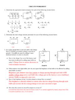
10 It is also the beginning of each cycle, subsequent changes in the FEEDBACK. ground reference for the BYPASS and FEEDBACK pins. pin voltage or current during the remainder of the cycle are ignored. V Regulator and V Shunt Voltage Clamp The V regulator charges the bypass capacitor connected to P Package (DIP-8B) the BYPASS pin to V by drawing a current from the voltage G Package (SMD-8B) D Package (SO-8C) on the DRAIN, whenever the MOSFET is off. The BYPASS pin is the internal supply voltage node for the LinkSwitch-TN . When 8. the MOSFET is on, the LinkSwitch-TN runs off of the energy S 1 8 S 1.