Transcription of Low profile shielded power inductors - Cooper …
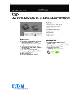
1 Effective November 2015. Technical Data 4149 Supersedes March 2007. SD53. low profile shielded power inductors Applications Desktop computers Notebook and laptop regulators LED and White LED drivers Digital cameras, media devices Battery power systems Environmental Data Storage temperature range (component): -40 C to +125 C. Product description Operating temperature range: -40 C to +125 C. (Ambient plus self temperature rise). Octagonal shape utilizes board space Solder reflow temperature: J-STD-020D. shielded drum core compliant Inductance range from uH to 100 uH HALOGEN. Current range from A to A Pb HF. FREE. mm x mm footprint surface mount package in a mm height Ferrite core material Halogen free, lead free, RoHS compliant Technical Data 4149 SD53.
2 Effective November 2015 low profile shielded power inductors .. Product Specifications Irms2 Isat3 DCR ( ) typical DCR ( ) maximum Part Number5 OCL1 ( H) 20% Part marking (A) (A) @ 20 C 20 C K-factor4. SD53-1R1-R A 48. SD53-2R0-R B 35. SD53-3R3-R C 28. SD53-4R7-R D 21. SD53-6R8-R E 20. SD53-100-R F 15. SD53-150-R G 12. SD53-220-R H 10. SD53-330-R I 8. SD53-470-R J 7. SD53-680-R K 6. SD53-101-R 100 L 5. 1. 1. Open Circuit Inductance (OCL) Test Parameters: 100 kHz, Vrms, Adc. 4. K-factor: Used to determine B p-p for core loss (see graph). B p-p = K*L* I, B p-p(mT), K: (K factor from table), 2. Irms: DC current for an approximate T of 40 C without core loss. Derating is necessary for AC currents. PCB layout, L: (Inductance in uH), I (Peak to peak ripple current in Amps).
3 Trace thickness and width, air-flow, and proximity of other heat generating components will affect the temperature 5. Part Number Definition: SD53-xxx-R. rise. It is recommended that the temperature of the part not exceed 125 C under worst case operating conditions SD53 = Product code and size; -xxx = Inductance value in uH; R = decimal point;. verified in the end application If no R is present then third character equals the number of zeros. 3. lsat: Peak current for approximately 30% rolloff @ 25 C. -R suffix = RoHS compliant. Dimensions (mm). 53. Part Marking: Line 1: (1st digit= inductance value per Part Marking Designator); (2nd digit= Bi-weekly production date code); (3rd digit= Last digit of the year produced), (4th digit= Internal manufacturing code).
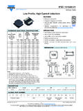
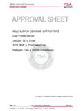
4 Line 2: 53=product size code). Do not route traces or vias underneath the inductor Packaging information (mm). Parts packaged on 13 diameter reel, 2,600 parts per reel. 2 SD53 Technical Data 4149. low profile shielded power inductors Effective November 2015.. Core loss vs. Bp-p 10. 500kH z 1 300kH z 1MH z 200kH z 100kH z Core Loss (W). 1 10 100 1000. Bp-p (mT). Temperature rise vs. total loss Inductance characteristics 3. Technical Data 4149 SD53. Effective November 2015 low profile shielded power inductors .. Solder reflow profile TP Table 1 - Standard SnPb Solder (Tc). TC -5 C. Max. Ramp Up Rate = 3 C/s tP Volume Volume Package mm3 mm3. Max. Ramp Down Rate = 6 C/s Thickness <350 350. TL < ) 235 C 220 C. Preheat t 220 C 220 C. A. T smax Temperature Table 2 - Lead (Pb) Free Solder (Tc).
5 Volume Volume Volume Tsmin Package mm3 mm3 mm3. ts Thickness <350 350 - 2000 >2000. < 260 C 260 C 260 C. 260 C 250 C 245 C. > 250 C 245 C 245 C. 25 C. Time 25 C to Peak Time Reference JDEC J-STD-020D. profile Feature Standard SnPb Solder Lead (Pb) Free Solder Preheat and Soak Temperature min. (Tsmin) 100 C 150 C. Temperature max. (Tsmax) 150 C 200 C. Time (Tsmin to Tsmax) (ts) 60-120 Seconds 60-120 Seconds Average ramp up rate Tsmax to Tp 3 C/ Second Max. 3 C/ Second Max. Liquidous temperature (Tl) 183 C 217 C. Time at liquidous (tL) 60-150 Seconds 60-150 Seconds Peak package body temperature (TP)* Table 1 Table 2. Time (tp)** within 5 C of the specified classification temperature (Tc) 20 Seconds** 30 Seconds**. Average ramp-down rate (Tp to Tsmax) 6 C/ Second Max.
6 6 C/ Second Max. Time 25 C to Peak Temperature 6 Minutes Max. 8 Minutes Max. * Tolerance for peak profile temperature (Tp) is defined as a supplier minimum and a user maximum. ** Tolerance for time at peak profile temperature (tp) is defined as a supplier minimum and a user maximum. Life Support Policy: Eaton does not authorize the use of any of its products for use in life support devices or systems without the express written approval of an officer of the Company. Life support systems are devices which support or sustain life, and whose failure to perform, when properly used in accordance with instructions for use provided in the labeling, can be reasonably expected to result in significant injury to the user. Eaton reserves the right, without notice, to change design or construction of any products and to discontinue or limit distribution of any products.
7 Eaton also reserves the right to change or update, without notice, any technical information contained in this bulletin. Eaton Electronics Division 1000 Eaton Boulevard Cleveland, OH 44122. United States 2015 Eaton All Rights Reserved Eaton is a registered trademark. Printed in USA. Publication No. 4149 All other trademarks are property November 2015 of their respective owners.