Transcription of LSI/CSI LS7366R
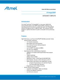
1 UL.. LSI/CSI . LSI Computer Systems, Inc. 1235 Walt Whitman Road, Melville, NY 11747. LS7366R . (631) 271-0400 FAX (631) 271-0405. A3800. 32-BIT QUADRATURE COUNTER WITH SERIAL INTERFACE. June 2014. GENERAL FEATURES: Operating voltage: 3V to (VDD - VSS). 5V count frequency: 40 MHz PIN ASSIGNMENT. 3V count frequency: 20 MHz TOP VIEW. 32-bit counter (CNTR). 32-bit data register (DTR) and comparator. f CKO 1 14 V DD. 32-bit output register (OTR). f CKi 2 13 CNT_EN. Two 8-bit mode registers (MDR0, MDR1). 12. for programmable functional modes. V SS 3 A. 8-bit instruction register (IR). SS/ 4 11 B. 8-bit status register (STR). SCK 5 10. Latched Interrupt output on Carry or Borrow or Compare or Index.
2 INDEX/. Index driven counter load, output register load or counter reset. MISO 6 9 DFLAG/. Internal quadrature clock decoder and filter. 8 LFLAG/. MOSI 7. x1, x2 or x4 mode of quadrature counting. Non-quadrature up/down counting. FIGURE 1. Modulo-N, Non-recycle, Range-limit or Free-running modes of counting Read and write commands cannot be combined. 8-bit, 16-bit, 24-bit and 32-bit programmable configuration For example, when the device is shifting out read synchronous (SPI) serial interface data on MISO output, it ignores the MOSI input, LS7366R (DIP), LS7366R -S (SOIC), LS7366R -TS (TSSOP) even though the SS/ input is active. SS/ must be - See Figure 1 - terminated and reasserted before the device will accept a new command.
3 SPI/MICROWIRE (Serial Peripheral Interface): Standard 4-wire connection: MOSI, MISO, SS/ and SCK. The counter can be configured to operate as 1, 2, 3. Slave mode only. or 4-byte counter. When configured as an n-byte counter, the CNTR, DTR and OTR are all config- GENERAL DESCRIPTION: ured as n-byte registers, where n = 1, 2, 3 or 4. LS7366R is a 32-bit CMOS counter, with direct interface for quadra- The content of the instruction/data identity is ture clocks from incremental encoders. It also interfaces with the automatically adjusted to match the n-byte configu- index signals from incremental encoders to perform variety of ration. For example, if the counter is configured as a marker functions.
4 2-byte counter, the instruction write to DTR . expects 2 data bytes following the instruction byte. For communications with microprocessors or microcontrollers, it If the counter is configured as a 3-byte counter, the provides a 4-wire SPI/MICROWIRE four standard bus I/Os same instruction will expect 3 bytes of data follow- are SS/, SCK, MISO and MOSI. The data transfer between a micro- ing the instruction byte. controller and a slave LS7366R is synchronous. The synchroniza- tion is done by the SCK clocks supplied by the microcontroller. Each Following the transfer of the appropriate number of transmission is organized in blocks of 1 to 5 bytes of data. A trans- bytes any further attempt of data transfer is ignored mission cycle is intitiated by a high to low transition of the SS/ input.
5 Until a new instruction cycle is started by switching The first byte received in a transmission cycle is always an instruc- the SS/ input to high and then low. tion byte, whereas the second through the fifth bytes are always interpreted as data bytes. A transmission cycle is terminated with The counter can be programmed to operate in a the low to high transition of the SS/ input. Received bytes are shifted number of different modes, with the operating in at the MOSI input, MSB first, with the leading edges (high transi- characteristics being written into the two mode tion) of the SCK clocks. Output data are shifted out on the MISO registers MDR0 and MDR1. Hardware I/Os are output, MSB first, with the trailing edges (low transition) of the SCK provided for event driven operations, such as clocks.
6 Processor interrupt and index related functions. 7366R-061814-1. I/O Pins: CNT_EN (Pin 13). Following is a description of all the input/output pins. Input. Counting is enabled when CNT_EN input is high; counting is disabled when this input is low. There is an internal pull-up A (Pin 12) B (Pin 11) resistor on this input. Inputs. A and B quadrature clock outputs from incremental encoders are directly applied to the A and B inputs of the LFLAG/ (Pin 8), DFLAG/ (Pin 9). LS7366R . These clocks are ideally 90 degrees out-of-phase Outputs. LFLAG/ and DFLAG/ are programmable outputs to flag signals. A and B inputs are validated by on-chip digital filters the occurences of Carry (counter overflow), Borrow (counter and then decoded for up/down direction and count clocks.)
7 Underflow), Compare (CNTR = DTR) and INDEX. The LFLAG/ is In non-quadrature mode, A serves as the count input and B an open drain latched output. In contrast, the DFLAG/ is a push- serves as the direction input (B = high enables up count, pull instantaneous output. The LFLAG/ can be wired in multi- B = low enables down count). In non-quadrature mode, slave configuration, forming a single processor interrupt line. the A and B inputs are not filtered internally, and are instan- When active LFLAG/ switches to logic 0 and can be restored to taneous in nature. the high impedence state only by clearing the status register, STR. In contrast, the DFLAG/ dynamically switches low with INDEX/ (Pin 10) occurences of Carry, Barrow, Compare and INDEX conditions.
8 Input. The INDEX/ is a programmable input that can be driven directly by the Index output of an incremental encod- The configuration of LFLAG/ and DFLAG/ are made through the er. It can be programmed via the MDR0 to function as one control register MDR1. of the following: LCNTR (load CNTR with data from DTR), RCNTR (reset MOSI (RXD) (Pin 7). CNTR), or LOTR (load OTR with data from CNTR). Input. Serial output data from the host processor is shifted into Alternatively, the INDEX input can be masked out for "no the LS7366R at this input. functionality". MISO (TXD) (Pin 6). In quadrature mode, the INDEX/ input can be configured to Output. Serial output data from the LS7366R is shifted out on operate in either synchronous or asynchronous mode.
9 In the the MISO (Master In Slave Out) pin. The MISO output goes into synchronous mode the INDEX/ input is sampled with the high impedance state when SS/ input is at logic high, providing same filter clock used for sampling the A and the B inputs multiple slave-unit serial outputs to be wire-ORed. and must satisfy the phase relationship in which the INDEX/. is in the active level of Logic 0 during a minimum of a SCK (Pin 5). quarter cycle of both A and B High or both A and B Low. In Input. The SCK input serves as the shift clock input for transmit- non-quadrature mode, the INDEX/ input is unconditionally ting data in and out of LS7366R on the MOSI and the MISO. set to the asynchronous mode.
10 In the asynchronous mode, pins, respectively. Since the LS7366R can operate only in the the INDEX/ input is not sampled and can be applied in any slave mode, the SCK signal is provided by the host processor phase relationship with respect to A and B. as a means for synchronizing the serial transmission between itself and the slave LS7366R . fCKi (Pin 2), fCK0 (Pin 1). Input, Output. A crystal connected between these 2 pins REGISTERS: generates the basic clock for filtering the A, B and INDEX/ The following is a list of LS7366R internal registers: inputs in the quadrature count mode. Instead of a crystal the fCKi input may also be driven by an external clock. Upon power-up the registers DTR, CNTR, STR, MDR0 and MDR1 are reset to zero.