Transcription of LTE Attach and Default Bearer Setup Messaging
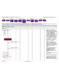
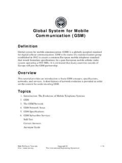
1 Telecommunication design systems engineering real-time and embedded systems LTE Attach and Default Bearer Setup Messaging 2012 Inc. All Rights Reserved telecommunication design systems engineering real-time and embedded systems LTE Attach Message Sequence Chart 2012 Inc. eNodeB MME HSS Initial UE Message SGW Initial Context Setup + Attach Accept + Activate Default Bearer Update Location Answer Create Session Request Create Session Response Update Location Request Initial Context Setup Response Attach Complete + Activate Default Bearer Accept Modify Bearer Request 2 telecommunication design systems engineering real-time and embedded systems S1AP: eNodeB MME S1AP Initial UE Message S1AP Initial UE Message Id: eNB UE S1AP ID Tracking Area Id Tracking Area Code Cell Id Attach Request EPS Attach type EPS Attach Combined EPS/IMSI Attach Identity IMSI Old GUTI EPS Encryption Algorithm Supported EPS Integrity Algorithm Supported Connection Request PDN Type: IPV4 Type.
2 Initial Attach Initial UE Message is the first message sent to the MME to establish a connection The eNode uses the eNB-UE-S1AP-ID to uniquely identify the UE EPS Attach type may be: EPS Attach : UE is attaching only to the 4G LTE network Combined EPS/IMSI Attach : The UE identity is specified is: IMSI: If the UE has is not registered with the network Old GUTI: Subsequent Attach requests identify the UE with the Old GUTI 2012 Inc. 3 telecommunication design systems engineering real-time and embedded systems S6A: MME HSS Diameter Update Location Request Diameter Update Location Request Command Code Update Location Request Application Id S6a interface application Origin Host Realm Destination Host Realm User Name IMSI RAT Type EUTRAN Visited PLMN Id MCC MNC MME updates the UE location with the HSS Origin and Destination are specified as Host and Realm (domain) The user name in the request is set to IMSI The Radio Access Technology is specified in the RAT Type It will be set to EUTRAN for LTE access The Visited PLMN is also included in the message 2012 Inc.
3 4 telecommunication design systems engineering real-time and embedded systems S6A: MME HSS Diameter Update Location Answer Diameter Update Location Answer Result Code: Success Subscriber Status: Service Granted Aggregate Maximum Bit Rate Maximum Requested Bandwidth Uplink Maximum Requested Bandwidth Downlink Access Restriction Data MSISDN APN Configuration Profile Called Station Id PDN Type IPV4 PDN GW Address PDN GW Name QoS Class Identifier QCI specifies BER, Priority, GBR Served Party IP Address 3 GPP Charging Characteristics Aggregate Maximum Bit Rate Maximum Requested Bandwidth Uplink Maximum Requested Bandwidth Downlink The HSS accesses the database and responds with user information to the MME The Aggregate Maximum Bit Rate (AMBR) occurs twice in the message: The first occurrence specifies the maximum bit rate for the Default PDP context The second occurrence specifies the data maximum data limit via the APN.
4 These limits are specified by the PDN APN configuration also includes: IP address of the PDN Gateway. This address is used to determine the Default route for the traffic towards the Internet IP address assigned to the UE (Served Party IP Address) 2012 Inc. 5 telecommunication design systems engineering real-time and embedded systems Default Bearer Establishment MME SGW: Create Session Request SGW PGW: Create Session Request The SGW asks the PGW to establish the Bearer SGW PGW: Create Session Response The PGW establishes the Bearer and responds back to the SGW MME SGW: Create Session Response The SGW responds back to the MME 2012 Inc. 6 telecommunication design systems engineering real-time and embedded systems S11: MME SGW GTP Create Session Request GTP Create Session Request IMSI RAT Type EUTRAN Sender F-TEID for Control Plane TEID MME IP Address EPS Bearer Id PDN Type IPV4 OR IPV6 Bearer Context ARP QCI QCI specifies BER, Priority, GBR MSISDN TAI MCC, MNC, TAC ECGI Contents MCC, MNC, ECI PGW S5/S9 Address for Control TEID PGW IP Address PDN IP Address APN PDN Address Allocation IP Address Assigned to UE Aggregate Max Bit Rate APN Limit Downlink and Uplink MME initiates the Default route establishment by asking the SGW to create a GTP tunnel The source is identified by the fully qualified endpoint identifier with the Tunnel Endpoint Identifier (TEID) and the MME IP Address The IP Address assigned to the UE is also included along with the downlink and uplink maximum data rates allowed at the APN level The TAI and ECGI (E-UTRAN Cell Group Identifier)
5 Information identify the current location of the user 2012 Inc. 7 telecommunication design systems engineering real-time and embedded systems S1AP: eNodeB MME S1AP Initial Context Setup Request NAS Attach Accept Activate Default Bearer Request Initial Context Request / Attach Accept/ Default Bearer Request S1AP PDU S1AP Initial Context Setup Request EPS mobility management messages NAS Attach Accept EPS session management messages Activate Default Bearer Request The next message from the MME is really a three-in-one. The message contains: SIAP Initial Context Setup Request A request to establish a context between the MME and eNodeB The message contains SGW tunneling information NAS Attach Accept This message acknowledges the successful Attach to the UE. The eNodeB will pass this message to the UE Activate Default Bearer Request The message initiates the Default Bearer Setup on the UE The eNodeB will pass this message to the UE 2012 Inc.
6 8 telecommunication design systems engineering real-time and embedded systems S1AP: eNodeB MME S1AP Initial Context Setup Request SIAP Initial Context Setup Request MME UE S1AP ID ENB UE S1AP ID Aggregate Max Bitrate (AMBR) Downlink Uplink eRABs to Setup eRAB ID QCI eRAB Max Bit Rate Downlink eRAB Max Bit Rate Uplink RAB Guaranteed Bit Rate Downlink RAB Guaranteed Bit Rate Uplink Transport Layer Address GTP TE ID UE Security Capability Encryption Algorithm Integrity Protection Algorithm Security Key The MME responds with MME UE S1AP ID that was received from the eNodeB in the initial UE message The message also contains the MME UE S1AP ID The message contains the maximum aggregate bit rate information. The message also contains the information about the Default eRAB. QCI to assign session priority The maximum bit rate for the eRAB Guaranteed bit rate for the eRAB Transport Layer Address assigns the IP Address for the user plane entity on the S-GW GTP TE ID identifies the S-GW end of the user plane tunnel The security capabilities specify the encryption and integrity protection algorithm to be used for the UE session 2012 Inc.
7 9 telecommunication design systems engineering real-time and embedded systems eNodeB MME UE eNodeB NAS Attach Accept NAS Attach Accept EPS Attach Result EPS Only T3412 TAI List Type One PLMN Partial TAI List PLMN TAC List GUTI MCC MNC MME Group Id MME Code M-TMSI GPRS Ready Timer The Attach Accept is carried as NAS payload in the Initial Context Setup Request The message specifies that the Attach has been successful. The terminal is attached to the EPS only ( LTE only, no SGSN registration) The T3412 timer specifies the maximum time between tracking area updates from the terminal The TAI list in the message specifies the PLMN and the Tracking Area Codes for all the registered tracking areas The message contains GUTI. GUTI uniquely identifies the UE with PLMN, MME Group, MMC code and the M-TMSI Finally, the GPRS Ready timer is included in the message.
8 The UE will be transitioned to IDLE if no activity is detected for this period 2012 Inc. 10 telecommunication design systems engineering real-time and embedded systems eNodeB MME UE eNodeB Activate Default Bearer Request Activate Default Bearer Request EPS Bearer Id EPS QoS QCI eRAB Max Bit Rate Downlink eRAB Max Bit Rate Uplink RAB Guaranteed Bit Rate Downlink RAB Guaranteed Bit Rate Uplink Access Point Name PDN Address The Attach Accept is carried as NAS payload in the Initial Context Setup Request The EPS Bearer id identifies the Bearer that needs to be activated The EPS QoS carries quality of service information: QCI to assign session priority The maximum bit rate for the Bearer Guaranteed bit rate for the Bearer The Access Point Name (APN) is included in the message The PDN IP address assigned by the HSS is passed to the UE 2012 Inc.
9 11 telecommunication design systems engineering real-time and embedded systems eNodeB MME Initial Context Setup Response S1AP Initial Context Setup Response MME UE S1AP ID eNB UE S1AP ID E-RAB Setup List E-RAB Setup Item E-RAB ID Transport Layer Address GTP TEID The eNodeB sends the Initial Context Setup Response message to the MME. The message confirms the establishment of the GTP tunnel on the S1-U interface The message contains information about the RABs that are being established at startup. The following information is present for each RAB The E-RAB ID The transport layer IP address on the eNodeB. The eNodeB GTP Tunneling ID (TEID) for the eNodeB side. 2012 Inc. 12 telecommunication design systems engineering real-time and embedded systems Completing the Attach and Default Bearer Activation eNodeB MME: Attach Complete + Activate Default Bearer Accept eNodeB transports Attach Complete and Activate Default Bearer Accept The message was received from the UE MME SGW: Modify Bearer Request Inform SGW about the eNodeB s user plane IP address and GTP TEID 2012 Inc.
10 13 telecommunication design systems engineering real-time and embedded systems Thank You Links Description EventStudio System Designer Sequence diagram based systems engineering tool. VisualEther Protocol Analyzer Wireshark based visual protocol analysis and system design reverse engineering tool. Telecom Call Flows GSM, SIP, , ISUP, LTE and IMS call flows. TCP/IP Sequence Diagrams TCP/IP explained with sequence diagrams. Telecom Networking Software Real-time and embedded systems, call flows and object oriented design articles. 2012 Inc. Thank you for visiting The following links provide more information about telecom design tools and techniques: 14