Transcription of Random Access Procedure - EventHelix.com
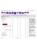
1 long Term evolution (LTE) Attach and Default Bearer Setup (Moving from Old to New MME)Cell SitesLTE/SAECNCellNewE-UTRANNew EPCOld EPCD atabasesUEeNodeBNew MMES erving GWPDN GWOld MMEHSSE ventStudio System Designer 511-Dec-12 07:45 (Page 1)Generated with EventStudio System Designer - This flow describes the setup of an LTE session. The connection establishment progresses through the following phases: (1)RRC Connection Establishment: The Radio Resource Control layer establishes a connection between the UE and the eNodeB. This Procedure is initiated with arandom Access with a preamble. This is follwed up with RRC connection establishment signaling on the UL-SCH and DL-SCH.
2 (2) Attach and Authentication: The UE now attaches to the Core Network. MME and Serving Gateway also establish a context for the UE. This phase also involvesauthentication for the UE as well are the Network. (3) Default Bearer Setup: Finally, the default bearer for data transfer is established. Default bearer session is established at the UE, eNodeB, MME, Serving GW andPDN Gateway. User data sessions is exchanged once the default bearer is setup. Note: Click on messages with blue titles for more details about message structure. Random Access Procedure Randomly select apreamble for sendinga RACH UE picks one of the 64 RACH preambles available in an LTE cell.
3 Thepreambles are generated from Zadoff-Chu Access PreambleRACH,Preamble,RA-RNTIThe terminal initiates a new session with the randomly selectedpreamble. The message identifies the UE with Access ResponseDL-SCH,RA-RNTI,Timing Advance,Uplink Resource Grant,Temporary C-RNTIThe eNodeB responds to the preamble with the " Random AccessResponse" message on the DL-SCH. The message addresses the UEwith a RA-RNTI but the message also assigns a Temporary message also sends a timing adjustment to correct the uplink timingfrom the UE. Optionally, the message may assign resources to theterminal for uplink Connection Establishment RRC Connection RequestUL-SCH,C-RNTI,UE-Identity = S-TMSI,Establishment Cause =mo-SignallingThe UE uses a UL-SCH allocation to send the RRC Connection Requestmessage.
4 The UE is identified by the C-RNTI that was assigned in theRandom Access Response message. The message contains a UEidentity (typically S-TMSI: MMEC+M-TMSI). The message also includesthe establishment cause for the RRC Term evolution (LTE) Attach and Default Bearer Setup (Moving from Old to New MME)Cell SitesLTE/SAECNCellNewE-UTRANNew EPCOld EPCD atabasesUEeNodeBNew MMES erving GWPDN GWOld MMEHSSE ventStudio System Designer 511-Dec-12 07:45 (Page 2)RRC Connection SetupDL-SCH,C-RNTI,SRB Identity,DL AM RLC,UL AM RLC,UL-SCH Config,PHR Config,Uplink Power ControleNodeB responds with an RRC Connection Setup message on theDL-SCH. The message creates the signaling radio bearer (SRB) inAcknowledged mode.
5 The message also contains configurationparameters for uplink RLC, UL-SCH, Power Head Room (PHR) andUplink Power and Authentication RRC Connection Setup Complete + NAS Attach RequestUL-SCH,Selected PLMN Identity,Old TAI,Old GUMMEI,Old GUTI,Selected PLMN IdentityThe UE signals the setup of the RRC connection. The message is alsoused to initiate the Attach Procedure by sending the Attach Request asNAS Payload. The attach message contains the old GUTI (GloballyUnique Temporary Identifier).Identify the MME from the OldGUMMEI Identify the MME from the Old GUMMEI (Globally Unique MMEI dentifier) reported by the Initial UE Message [Attach Request + PDN Connectivity Request]id = eNB UE S1AP ID,Tracking Area Id = TAI+Cell Id,EPS Attach Type = EPS Attach,Identity = Old GUTI,EPS Encryption and IntegrityAlgorithms,Selected NetworkThe Attach message is sent in the Initial UE message to the MME overthe S1AP interface.
6 The "Attach Request" is embedded in the Initial UEMessage. The message also includes the PDN Connectivity Requestmessage. The Tracking Area Identify (TAI) and E-UTRAN Cell GlobalIdentifier (ECGI) are also included. Note that the eNodeB uses theeNB-UE-S1 APID to uniquely identify the Request [Attach Request]Old GUTIS ince the UE identified itself with GUTI and the MME has changed sincedetach, the new MME uses the GUTI received from the UE to derive theold MME, and send an Identification Request (old GUTI, complete AttachRequest message) to the old MME to request the ResponseThe old MME responds with Identification Response (IMSI, unused EPSA uthentication Vectors, KSIASME, KASME)Authentication Info RequestAuthentication Info AnswerLong Term evolution (LTE) Attach and Default Bearer Setup (Moving from Old to New MME)
7 Cell SitesLTE/SAECNCellNewE-UTRANNew EPCOld EPCD atabasesUEeNodeBNew MMES erving GWPDN GWOld MMEHSSE ventStudio System Designer 511-Dec-12 07:45 (Page 3)Ciphered Options RequestSince the UE has set the Ciphered Options Transfer Flag in the AttachRequest message, the ciphered Options PCO or APN or both, shallnow be retrieved from the Options ResponseUpdate Location RequestOrigin,Destination,User Name = IMSI,Visited PLMN IdSince the MME has changed since the last detach, the MME sends anUpdate Location Request message to the HSS. The MME capabilitiesindicate the MME's support for regional Access restrictions Type indicates this is Attach LocationIMSI,Cancellation TypeThe HSS sends Cancel Location to the old MME.
8 The old MMEacknowledges with Cancel Location Ack and removes the MM andbearer Location AckIMSIU pdate Location Request AnswerIMSI,Aggregate MBR (DL and UL),MSISDN,APN = PDN GW Address, QCI, Charging, Aggregate MBR (DL, UL)The HSS acknowledges the Update Location message by sending anUpdate Location Answer message to the new MME. The SubscriptionData contains PDN subscription contexts. Each PDN subscriptioncontext contains an 'EPS subscribed QoS profile' and the subscribedAPN-AMBR . The new MME validates the UE's presence in the (new)TA. If all checks are successful then the new MME constructs a contextfor the Radio Bearer Setup GTP Create Session RequestSender F-TEID for Control Plane,ARP,QCI,MSISDN,TAI,PGW IP Address,PDN IP Address,APN,IP Address Assigned to UEMME initiates the default route establishment by asking the SGW tocreate a GTP tunnel.
9 The APN specified by the UE is used for defaultbearer activation. The IP Address assigned to the UE is also includedalong with the downlink and uplink maximum data rates allowed at theAPN a new entry in EPSB earer table long Term evolution (LTE) Attach and Default Bearer Setup (Moving from Old to New MME)Cell SitesLTE/SAECNCellNewE-UTRANNew EPCOld EPCD atabasesUEeNodeBNew MMES erving GWPDN GWOld MMEHSSE ventStudio System Designer 511-Dec-12 07:45 (Page 4)Map from APN to PDNG ateway Bufferdownlinkpackets Create Default Bearer RequestIMSI,MSISDN,APN,Serving GW AddressServing Gateway sends Create Default Bearer Request message to thePDN a newentry in its EPSbearer contexttable andgenerates aCharging Id The new entry allows the P GW to route user plane PDUs between the SGW and the packet data network, and to start Default Bearer RequestPDN GW User Planeaddress,PDN GW TEIDs User andControl Plane,EPS Bearer Identity andQoSDownlink DataServing Gateway receives the first downlink data block.
10 This block isbuffered at the Serving GW".Create Default Bearer RequestInitial Context Setup Request [Attach Accept, Activate Default Bearer Request]MME responds back to the eNodeB with a message containing threemessages: SIAP Initial Context Setup Request, NAS Attach Accept andActivate Default Bearer and process InitialContext Setup Request The message is identified by the S1AP id that was sent in the initial UEmessage. The message contains maximum bit rate information for theUE. Quality of service information for the new eRAB is also specified(QCI, maximum bit rate downlink and uplink). The information receivedin this message will be used to setup radio resources for the and process AttachAccept The message is extracted from the NAS payload of the Initial ContextSetup Request message.